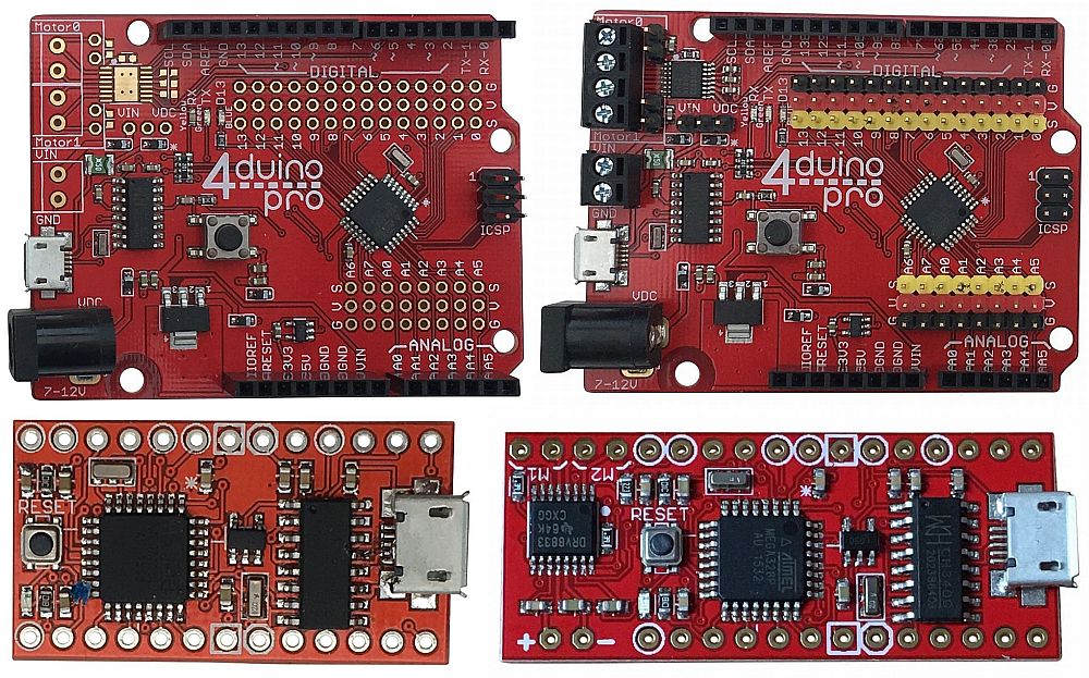
4duino – Arduino Uno Compatible Products
Purchase 4duino here
4tronix have created a range of Arduino compatible boards with our own brand of magic.
All members of this new range are fully compatible with Arduino Uno software, and the 2 larger Uno form factor boards are fully hardware compatible as well
In addition, the 4duino range features:
- 16MHz ATMega328P-AU processors
- 14 Digital I/O pins (5 of which can be PWM – Pulse Width Modulated)
- 8 Analog input pins (6 of which can be Digital I/O as well)
- Built-in 5V regulators (check individual specifications for current ratings)
- Reset buttons
- Full USB interface (using CH340 interface chip)
- Micro-USB connector
The 4duino Uno full-size products also have:
- DC Jack for powering via up to 11V
- Coloured coded pins (Pro) or available holes for 3-pin sensors (GVS – Ground, Volts, Signal) for all 22 I/O pins
Schematics
You can download the schematics for these boards from the following links
Programming 4duino Boards
As these boards are fully compatible with the standard Arduino Uno, you should follow the instructions and reference examples at www.arduino.cc to download programming software, libraries, example files and lots of tutorials.
The additional motor drivers on the Pro versions of these boards you will need the pin information and a brief example:
- Motor A Pins: D5 and D9
- Motor B Pins: D6 and D10
The motor driver is a standard dual H-Bridge (DRV8833 chip):
- Setting one pin High and the other Low will drive the motor one direction
- Swapping High and Low will drive the motor in the opposite direction
- Setting both to Low, or both to High will stop the motor
- (setting both High will brake the motor quickly, setting both Low will allow the motor to coast to a stop)
- The following code, drives one motor forwards, then backwards, then stops:
// the setup routine runs once when you press reset:
void setup() {
// initialize the digital pins we will use as an output.
pinMode(D5, OUTPUT);
pinMode(D9, OUTPUT);
}// the loop routine runs over and over again forever:
void loop() {
// Forwards, then wait 500ms
digitalWrite(D5, HIGH);
digitalWrite(D9, LOW);
delay(500);
// Reverse, then wait 500ms
digitalWrite(D5, LOW);
digitalWrite(D9, HIGH);
delay(500);
// Stop, then wait 500ms
digitalWrite(D5, LOW);
digitalWrite(D9, LOW);
delay(500);
}
Powering the Boards
The 4Duino range can be powered by putting between 7 and 10V into the DC Jack connector (not available on the Mini or Mini Pro). It can also be powered with 5V on the USB connector – eg. connecting directly to a PC. Finally it can be powered by putting 5V onto the 5V signal.
Powering the Motors
The motors use a separate power supply from the Arduino processor. This is because the 5V regulators cannot deliver as much current as you may need to use, but this depends on the motors used.
4Duino Pro: You can select using jumper J3 whether the motor power is taken from the DC Jack input or the separate 2-pin screw terminal. The full voltage on the selected input is used to drive the motor. Note that the Ground signal is common to the Arduino chip, the DC Jack input and the 2-pin terminal.
4Duino Mini Pro: The power for the motors is taken from the end pin labelled ‘+’. For low power motors this “could be” connected directly to the 5V pin on the board, but probably best to connect to the Vin pin.
Download the CH340 Drivers for your OS
- Windows
- Mac
- Raspberry Pi/Linux and also see Jarle’s blog for Raspberry Pi installs and usage
4duino Uno

This is software and hardware compatible with an Arduino Uno. You can use all the same addon Shields and get the same performance. In addition, we have made the extra 2 Analog pins available via the holes on the board into which you can solder headers if required.
These extra analog pins can be used within the Arduino IDE as A6 and A7. Note that they are analog ONLY – there is no ability to do a digital read or write on them and there is no ability to set pullup resistors.
Currently, the 4duino Uno is a depopulated 4duino Uno Pro board – so you can upgrade it to the full Pro specification with some surface mount soldering! Adding the GVS headers is much easier and a great upgrade though.
The USB interface is via the CH340 chip which has drivers available for all operating systems here.
On board 5V regulator: 1A
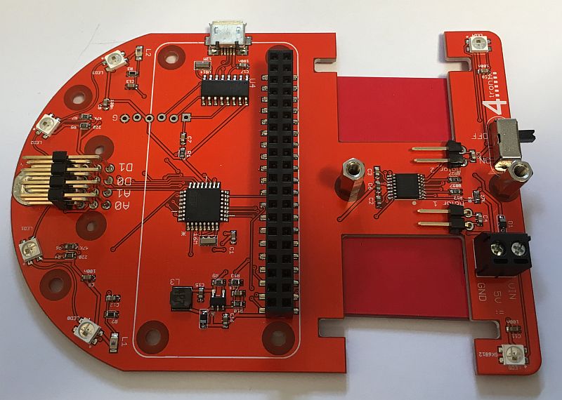
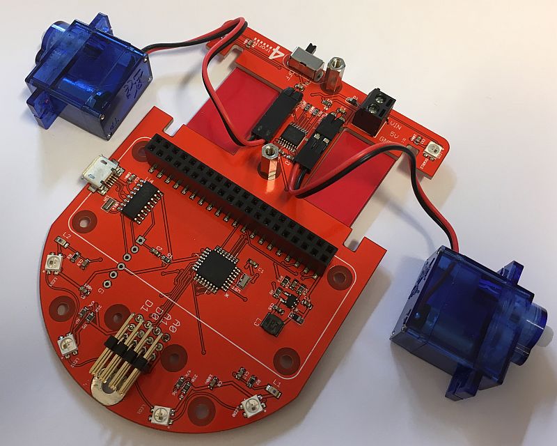
4duino Uno Pro

This is the fully populated version of the board that includes an integrated 2-channel H-bridge motor driver (the DRV8833).
The 4duino Uno Pro is fully hardware and software compatible with an Arduino Uno. You can use all the same addon Shields and get the same performance. In addition we have added colour-coded GVS headers for all the I/O pins including the additional 2 analog pins, A6 and A7. Note that these additional analog pins are analog ONLY – there is no ability to do a digital read or write on them and there is no ability to set pullup resistors.
The great news is that the Pro version also includes a 2-channel full H-bridge motor driver so you can control motors without requiring any addition shields or messy wiring. In fact, with the GVS headers installed, together with the motor drivers, the 4duino Uno Pro is like combing an Uno, sensor shield and motor shield into a single board!
On board 5V regulator: 1A
Motor control Pins:
- Motor 0: D5, D9
- Motor 1: D6, D10
4duino Mini

The 4duino Mini is an extremely small version of the Arduino Uno with all the same I/O pins, USB interface, reset button and voltage regulator.
All 22 I/O pins are brought out to the board edge where you can connect directly to them or solder in the provided headers.
The extra 2 analog pins can be used within the Arduino IDE as A6 and A7. Note that they are analog ONLY – there is no ability to do a digital read or write on them and there is no ability to set pullup resistors.
It is intended that headers, if fitted, are fitted so that the underside of the board is visible during use. This side of the board has no components and so has more room for labelling of all the pins.
Certain pins have symbols around them:
- Circle: this is a digital pin that is capable of PWM
- Octagon: These are the Ground connections
- Square: One of these is 5V and is either a 5V input to the board, or a 5V output if you are using the onboard 5V regulator. The other square is the VIN for the voltage regulator. This can be from 6V to 9V. So if you are using this board with 4xAA batteries you would have a 6V nominal voltage which you apply to the VIN and GND inputs. You can then use the 5V pin to power the rest of your ciruit (up to 150mA)
On board 5V voltage regulator: 150mA
- Dimensions: 33.75 x 18.5 x 1mm
- Weight: 2g
4duino Mini Pro

The 4duino Mini Pro is a slightly longer version of the 4duino Mini. The extra length is used to house the dual H-Bridge motor driver and associated components, as well as the motor power input and motor power outputs. The remainder of the board is identical to the 4duino Mini
All 22 I/O pins are brought out to the board edge where you can connect directly to them or solder in the provided headers.
The extra 2 analog pins can be used within the Arduino IDE as A6 and A7. Note that they are analog ONLY – there is no ability to do a digital read or write on them and there is no ability to set pullup resistors.
It is intended that headers, if fitted, are fitted so that the underside of the board is visible during use. This side of the board has no components and so has more room for labelling of all the pins.
Certain pins have symbols around them:
- Circle: this is a digital pin that is capable of PWM
- Octagon: These are the Ground connections
- Square: One of these is 5V and is either a 5V input to the board, or a 5V output if you are using the onboard 5V regulator. The other square is the VIN for the voltage regulator. This can be from 6V to 9V. So if you are using this board with 4xAA batteries you would have a 6V nominal voltage which you apply to the VIN and GND inputs. You can then use the 5V pin to power the rest of your ciruit (up to 150mA)
On board 5V voltage regulator: 500mA (peak)
- Dimensions: 43.75 x 18.5 x 1mm
- Weight: 2.6g
Motor control Pins:
- Motor 2: D5, D9 (labelled on PCB as M2, but is M0 to be consistent with 4duino Uno Pro)
- Motor 1: D6, D10
- The + and – pins on the opposite side from the Motor pins are what is used to power the motors. You need to wire these to your board power input or raw 5V or whatever if you need to power the motors.