Assembly Instructions
I think building the fuselage is the place to start, to get the hang of the construction method.
Downloads
Fuselage
Don’t solder anything just yet.
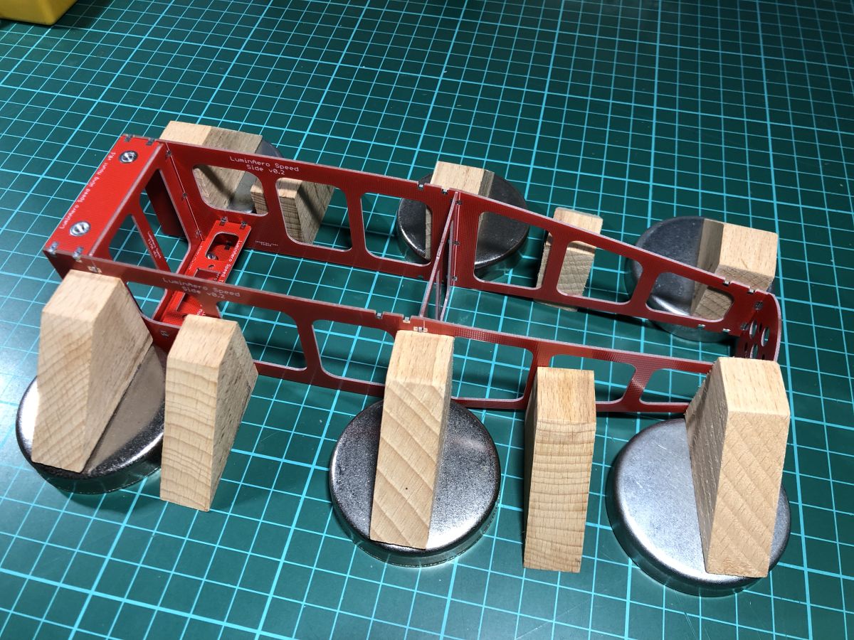
I suggest that you place the two sides vertically on your building board, place F1 and two of the F2 in place then hold it together with elastic bands. You don’t want to squeeze it too tight. Then fit the wing and hatch mounts and the servo mount.
Place a bit of weight over the top to hold everything flat to the table, and check everything is square.
Once you’re happy, quickly solder one or two pads on each PCB join, so it holds itself together. Note that just tacking single joints like this makes each joint very weak, so don’t put any twist or pressure on it.
Check again that everything is straight and true, then solder everything else. There’s a lot of solder joints to do. Top and bottom, inside and outside, etc.
You should now have a solid monocoque.
You can download plans in PDF format for the fuselage sides. These can be printed full size on multiple A4 sheets, or just use the dimensions given to cut them out – all edges are straight lines so it’s easy.
Cut the two sides out, following the plan and ensure they are identical. Then line them up one at a time against the PCB assembly. When you’re sure it’s in the correct place, press the balsa against the PCB joins to mark where to remove bits of balsa. This will allow the balsa sheet to fit directly against the PCB.
[Photos required]
Use epoxy and spread it over the PCB where the balsa contacts, then attach both sides and clip them against PCBs. I use lots of small bulldog clips for this.


Wing
The wing is much more fiddly than the fuselage as the pieces are smaller and there’s a lot of them.
I find it easiest to start from one side and work my way across to the middle, then back out to the other side. The images below show working from Port to Starboard.
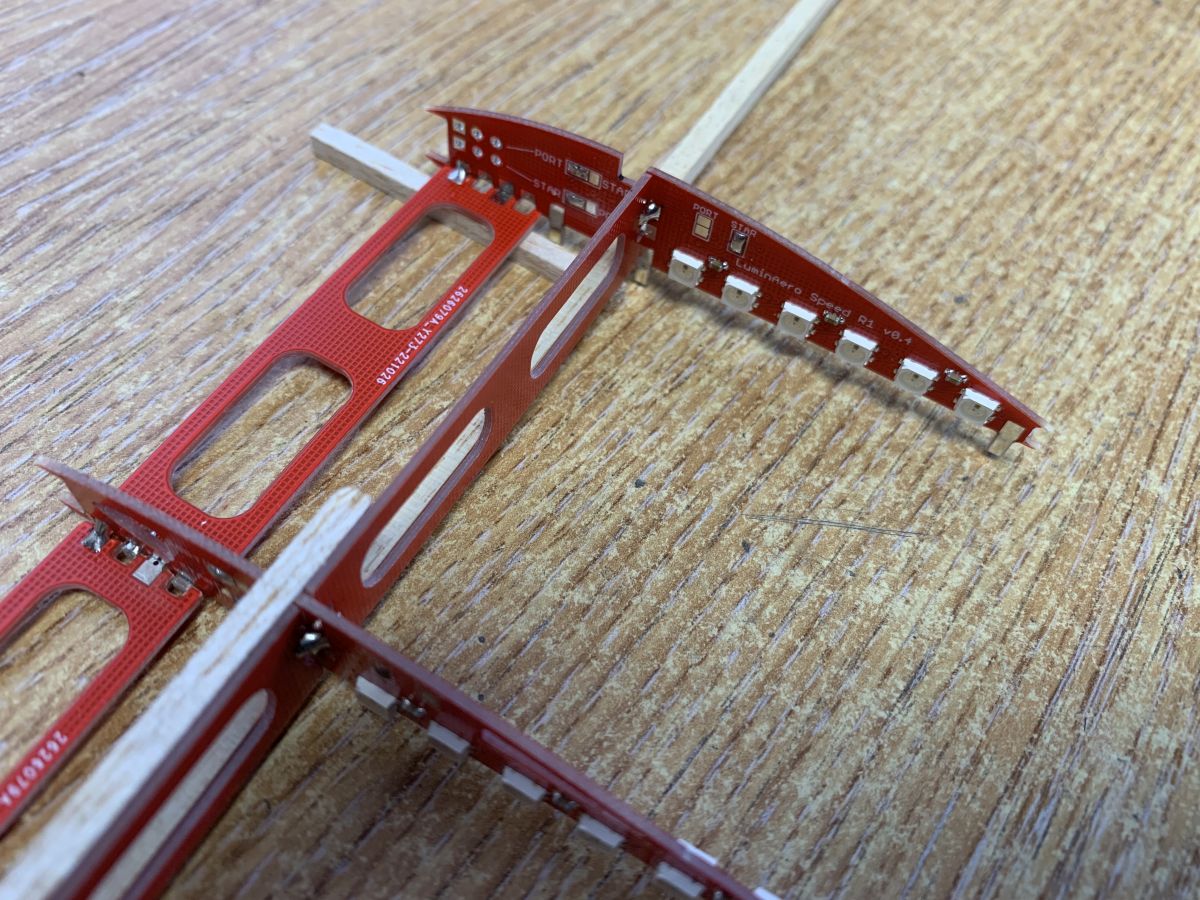
1 Check the parts are correct

Starboard on right from wingtip at top to root rib at bottom.
Note the different configuration jumper settings on each rib and the tabs on the root ribs

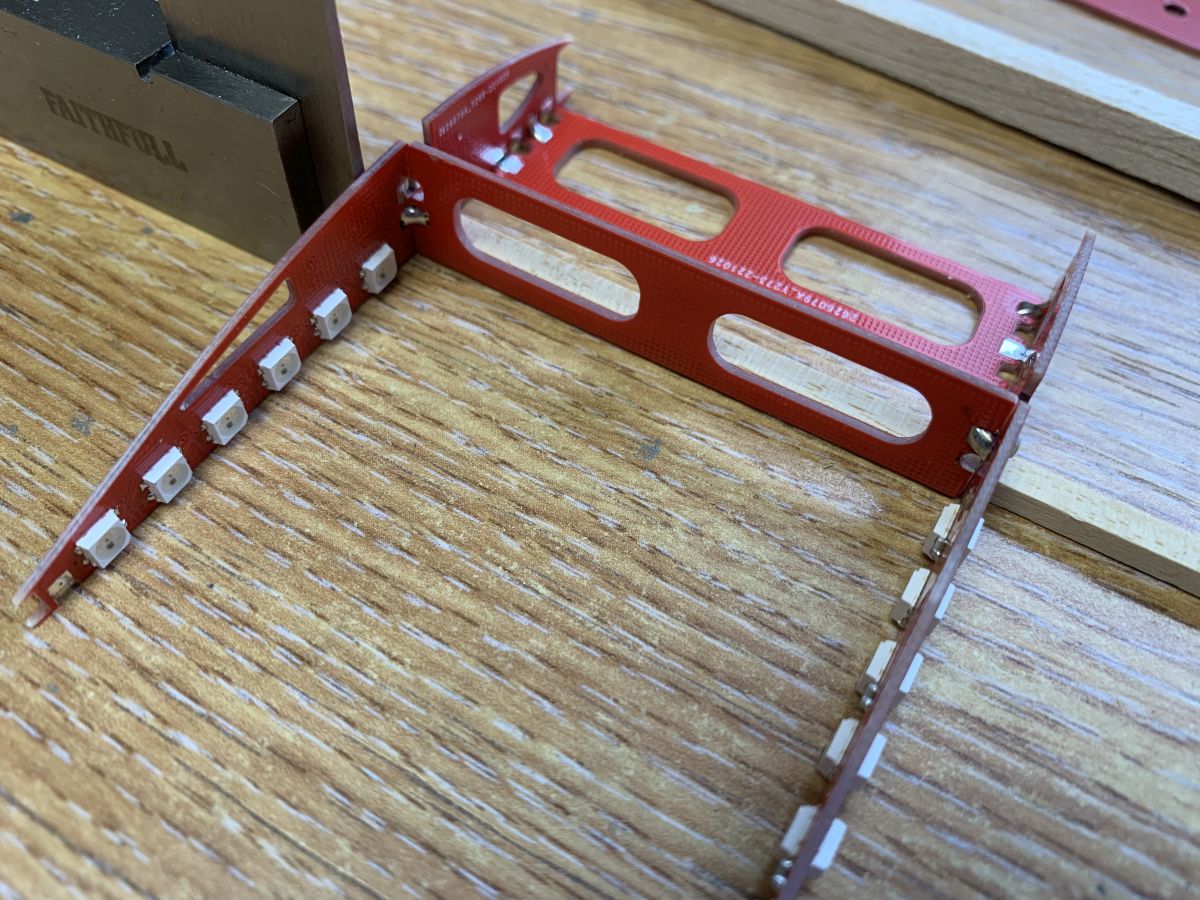
Then solder one joint of each onto the first main rib
Use finger pressure and soldering iron to melt solder and ensure both braces are fully against each rib to ensure they are square


Again ensure that both ends are fully against the ribs
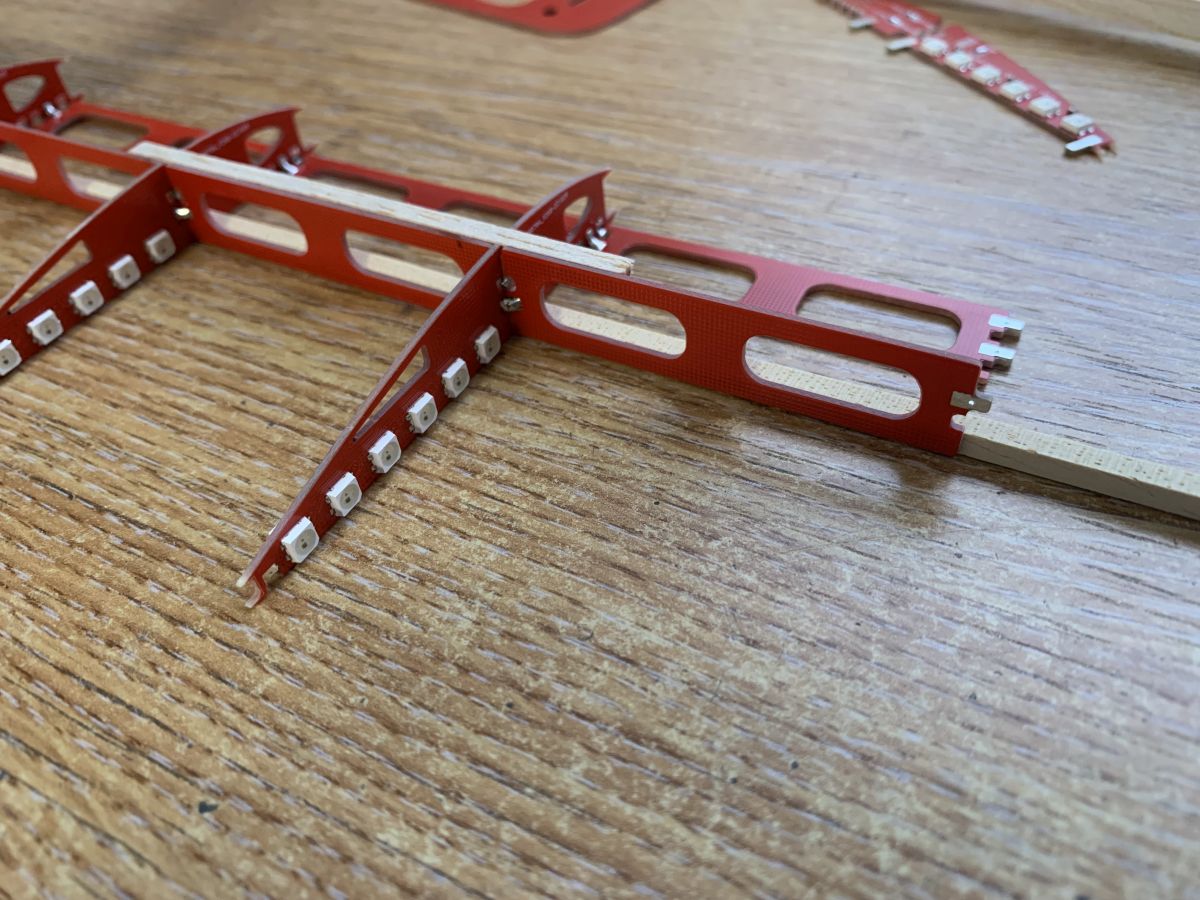
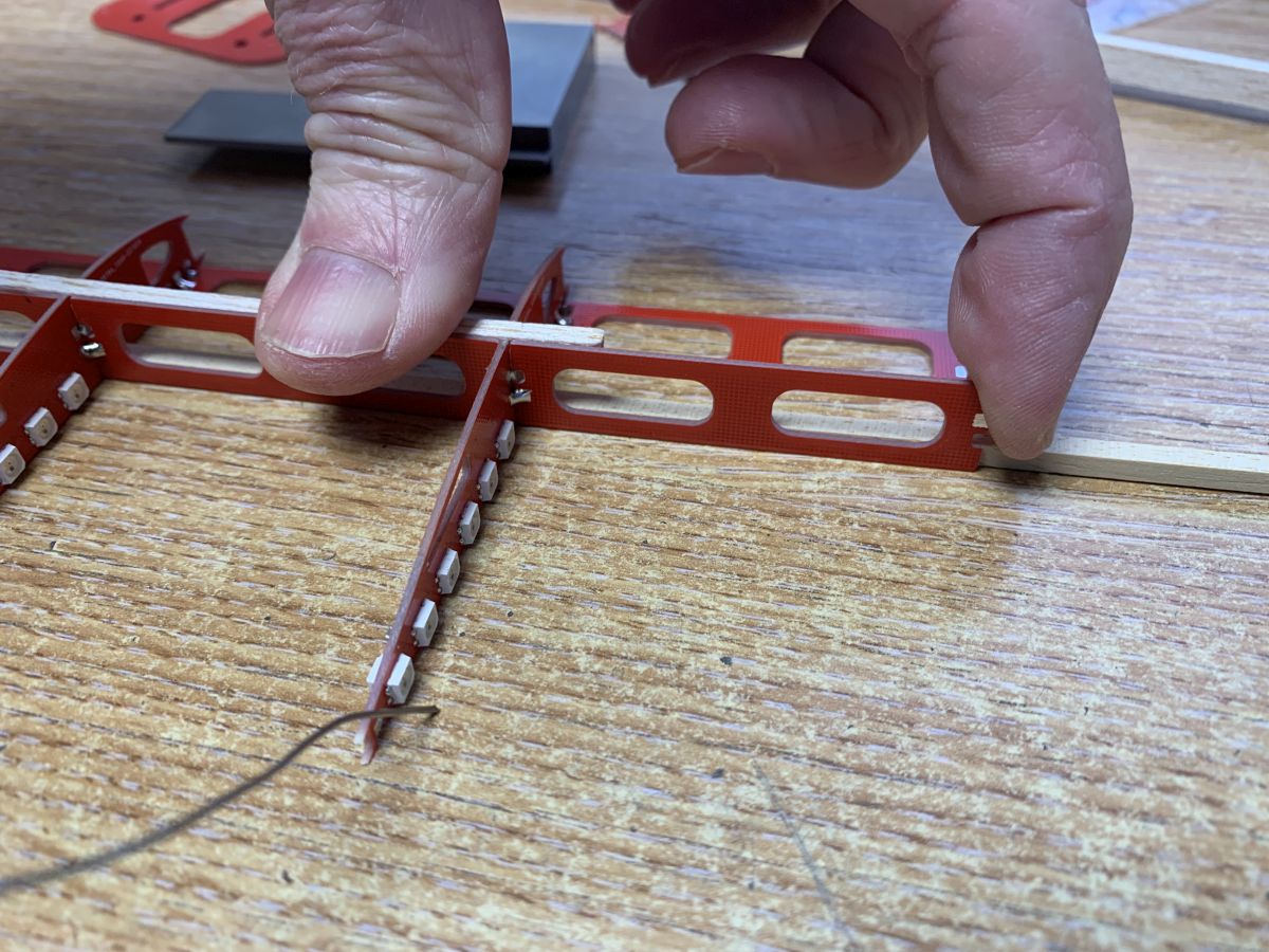
At the same time, use a soldering iron in the other hand to melt the solder joints

Take particular care to ensure this rib is square in all directions
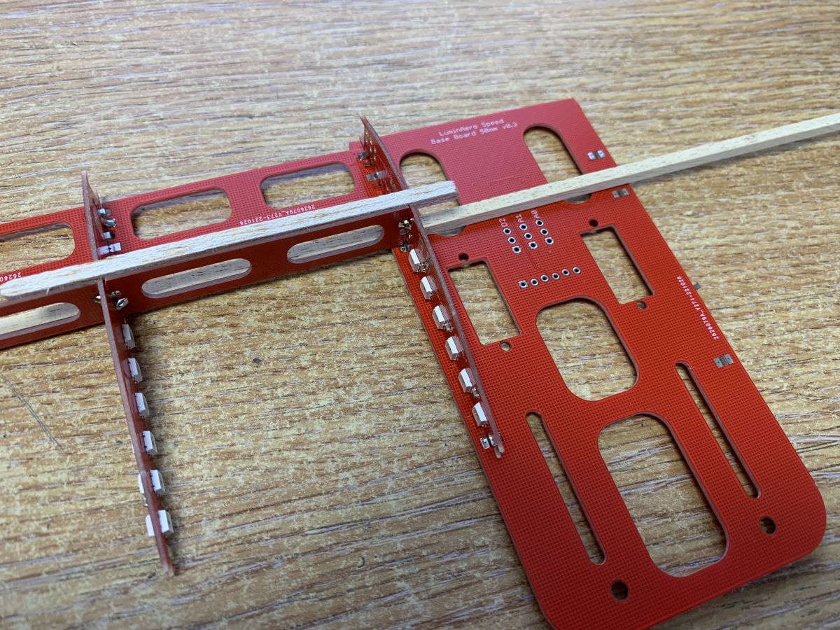
Note the orientation of the base, with the components underneath
Continue adding ribs, starting with the Starboard root rib, all the way to the wing tip.
Ensure that the higher tab on the vertical web braces is on the inboard side – this means the PCBs are the opposite way around from the port wing.
Check that everything is totally square and flat to the building board – you will need a gap in the building board, or use two boards, to enable the centre section to lie below the level of the rest of the wing.
When everything is square, solder up all the joints. Remember that every joint (except those on the edges of PCBs) has four solder positions: top, bottom, left, right.