Using RoboHAT with Initio
Click on any image to enlarge
You should already have followed the instructions for assembling the chassis here.
In this section we will add the RoboHAT controller, the obstacle sensors, line sensors and the pan/tilt assembly with ultrasonic sensor.
1. Fitting the RoboHAT to the Raspberry Pi
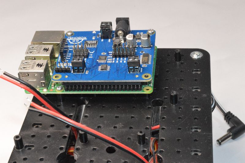
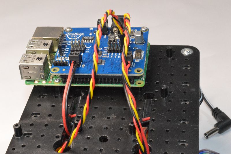
Screw one of the support pillars to the underneath of the RoboHAT at the front (under the RoboHat logo). Then plug the RoboHAT onto the Raspberry Pi.
Push the RoboHAT carefully onto the GPIO pins of the Raspberry Pi, ensuring the pins are placed correctly as shown in the photo above
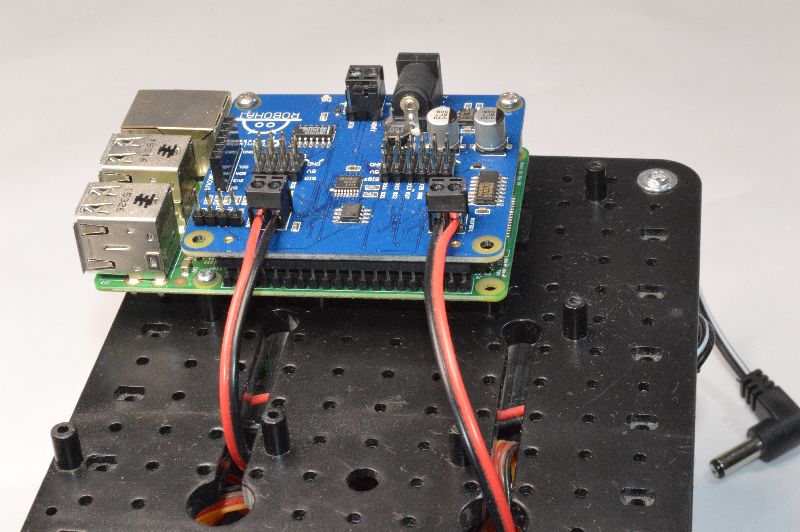
Connect the motor wires as shown. Red – Black – Black – Red
It won’t damage it if you connect them differently, but the example programs won’t go the direction that you would expect

Plug the Black/White cable with the DC Jack into the left-most pins on the switch PCB on Initio and the DC Jack end into the RoboHAT as shown above.
There will be a spare cable with Red and Black wires. This is not required for the Raspberry Pi build and should be removed so the ends don’t short.
Check all the wiring again very carefully, then now is a good time to see if the Pi powers up and you can control the motors.
Use 6xAA batteries. These should be good quality rechargeable batteries. We recommend Energizer Extremes or Eneloops
Connect a monitor, keyboard and mouse to the Raspberry Pi, plug in your SD card and switch on. The green light near the On/Off switch should turn on, the LEDs on the Pi should start flashing and the booting sequence should appear on the monitor. If not, switch off and double check the wiring.
Instead of using the batteries, you can plug a micro-USB cable directly into the connector on the Pi. This is an excellent way to get started and allows you to test everything (except the motors, which may turn but only slowly) without using batteries.
2. Mounting Obstacle Sensors

Check that each sensor has 2 mounting collars. Screw one onto the body of the sensor, leaving room at the front for the second one

Push the sensor through from the rear of the mounting bracket and screw on the second collar. Feed the wires up through the holes in the top plate

Repeat for the second side
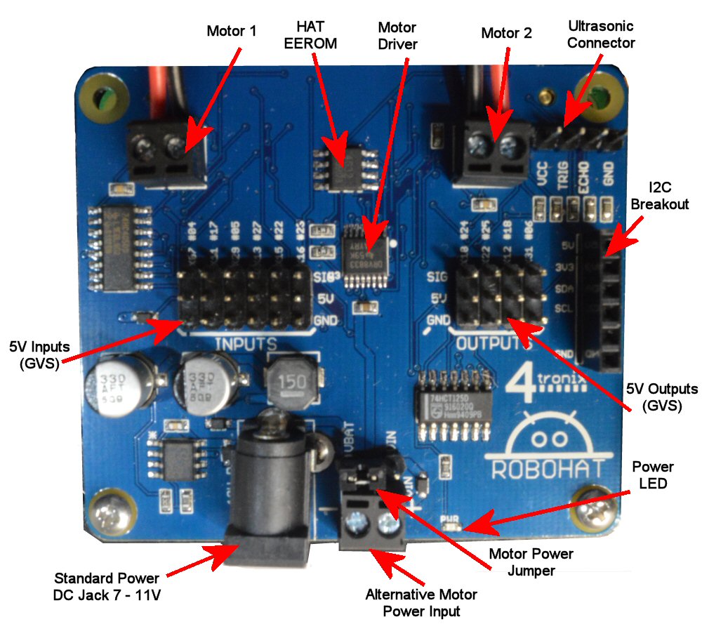
Connect to the RoboHAT INPUTs
- Left sensor to Pin 7 (marked x07 or #04)
- Right sensor to Pin 11 (marked x11 or #17)
The wire colours from the obstacle sensor are:
- Black: Gnd
- Red: 5V
- White or Yellow: Signal
Make sure you connect them to the correct pins on the RoboHAT
3. Mounting the Line Sensors

First, take the 30cm female-female jumper strip of 10 wires and split it into three strips:
- Brown, Red, Orange, Yellow (this is for the Ultrasonic Sensor)
- Green, Blue, Purple (this is for the Left Line Sensor)
- Grey, White, Black (this is for the Right Line Sensor)

Next, prepare the two Line Sensors and 2 of the 3x8PB screws as shown

Screw the line sensors in position as shown, using the screwhole in the middle of the circuit board

Connect the Green, Blue, Purple wire to the Left Sensor and the Grey, White, Black cable to the Right Sensor
** Note some sensors have the pins in order 5V, Signal, Gnd; other have them in order Signal, 5V, Gnd – make sure you know which wire colour is connected to which.
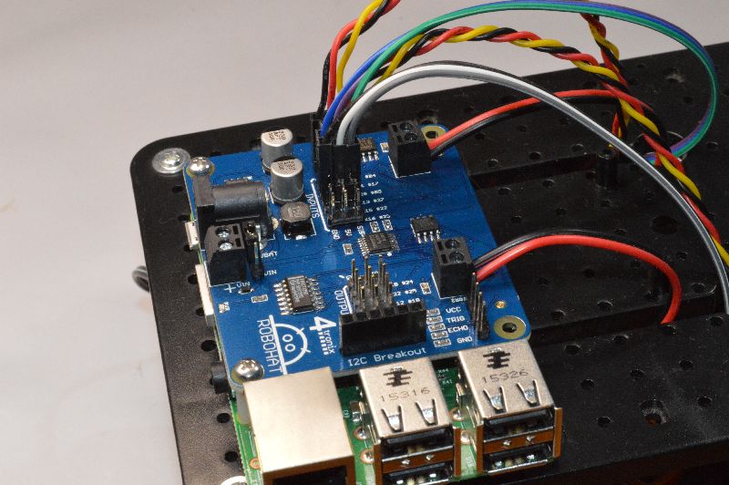
Connect the sensors to the RoboHAT
- Left sensor to Pin 29 (marked x29 or #05)
- Right sensor to Pin 13 (marked x13 or #27)
4. Connecting the Pan/Tilt Assembly

This is now supplied fully assembled with the Initio Ultimate kit. If you have an unassembled one, then please visit the assembly instructions here (opens in new window)
Take 4 of the 2.0x6PB screws (these are the smallest ones in the packet and there are 6 of them)

Screw the base of the pan/tilt assembly to the upper plate in the position shown
Rotate the pan/tilt carefully left and right to access the screw holes

Connect the Pan servo (bottom servo) to Pin 22 (marked x22 or #25)
Connect the Tilt servo (upper servo) to Pin 18 (marked x18 or #24)
Note the colours of the servo wires and ensure they are connected correctly:
- Black: Gnd
- Red: 5V
- Orange or White: Signal
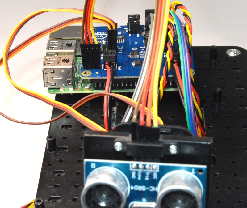
5. Connecting the Ultrasonic Sensor
NOTE: More recent kits use a specially purchased ultrasonic sensor which has the connection pins at the front, instead of at the rear as shown below. If you have one of these, then simply use 2 small screws (included) to fit the sensor securely to the mounting plate. If your connection pins are at the back, please follow the instructions below. The wiring is the same in either case.

For this you will need the mounting plate, saddle clamp and the final 2 of the 2.0x6PB screws used in step 4

Push the 4-way 30cm female-female cable that you made in Step 3 onto the top of the ultrasonic sensor:
- Brown: Gnd
- Red: Echo
- Orange: Trig or Ping
- Yellow: 5V or VCC

Screw the saddle clamp over the cable terminals as shown above

Clip the whole assembly to the front of the Pan/Tilt assembly as shown above
Note that you can purchase additional clip-on mounts so you could mount a camera on one and simply clip it off to change from Ultrasonic to Camera
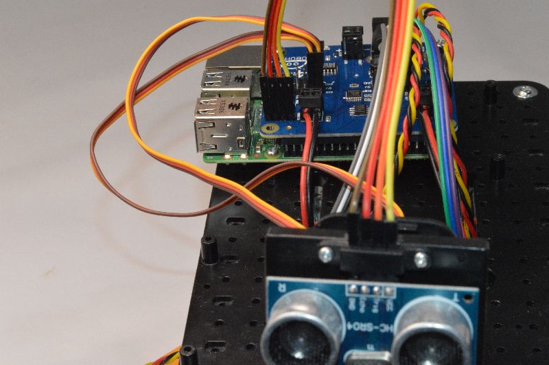
Connect the other end of the cable into the ultrasonic pins located between the 2 motor terminals
Ensure that Brown is Gnd, and they are in the order as shown
The main build of your Ultimate Initio Kit for the Raspberry Pi is now complete.
6. Connecting the Wheel Sensors (Optional)
Note that the wheel sensors require additional code to operate properly that is not included in the python library.
It is recommended that you do not fit these until you are familiar with the operation of the rest of the robot.
If you want to fit them, use Pins 15 and 16 (marked x15, x16 or #22, #23)
For each Wheel Sensor, connect:
- Black to Gnd
- Red to 5V
- Orange or Brown to the selected pin (in fact, each wheel has 2 sensors that are slightly out of phase so you can get direction of travel from them, but you will then need 2 pins for each sensor)
- DO NOT connect the sensor wires directly to GPIO pins on the Raspberry Pi as they are 5V signals. Always use beffered inputs as on the RoboHAT
It is recommended to leave the wheel sensor cables unconnected to start with