#FreePiStuff No.1
Pi-Sense 0.3 Prototype Kit
** THIS OFFER IS NOW CLOSED ***
What is it?
This a proto-type version of the upcoming 4tronix PiRoCon robotic controller board – which will be very different from this board (this one doesn’t include motor drivers for a start). This was the first design committed to a PCB, so a few mods are on the board but they do the job intended very well. Would seem a shame to let them go to waste, so I’d like them to be used.
This prototype kit features:
- 5V regulated power supply for the Pi, the board itself and any attached peripherals
- All 8 un-allocated GPIO pins brought out to 3-way headers with power, ground & signal
- 4 of these GPIO include bidirectional, 5V-3V3 level-shifters
- Level-shifters can be removed, or allocated to different pins by removing jumpers and replacing with jumper wire
- SPI female header for the SPI pins
- I2C/UART header for the obvious!
- Red LED for 5V, Yellow LED for 3V3
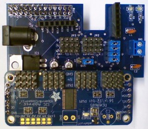
- Connectors to allow plugging on the Adafruit 16-Channel Servo/PWM Driver using PCA9685 chip (as shown in the photo above.
What do I get for Free?
You will receive a prototype PCB with some mods on. All the surface mount components are ready-fitted, together with the 8, 3-way header pins (as the mods are on the back of these).
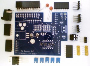
Loose components included for you to solder and complete the kit are:
- 26-pin GPIO header
- 2 x 100nF capacitors
- 2 x 10K resistor networks
- DC Jack socket
- L4940V5 regulator
- 8-pin female header
- 3 x 6-pin female headers
- 4×2 male header block
- 3×1 male header
- 2-pin screw terminal
- 5 x 0.1” jumpers
- Metal hex spacer and screws to mount the board to the Pi (not shown)
What don’t I get for Free?
You won’t get:
- Any guarantee
- Postage outside UK (£3.90 for standard airmail, £10.02 for registered)
- DC Plug to plug into the jack socket
- Adafruit PCA9685 board – see www.ebay.co.uk/itm/161107058694
OK Sounds Good – How do I build it?
There’s no particular order, and whichever order you choose, you will end up wishing that a certain component wasn’t there when you are adding another. This is my preferred order:
- Solder the small orange 100nF capacitors C1 and C2. It doesn’t matter which way round
- Solder the 2 yellow resistor networks. You need to get these in the right holes and the right way round
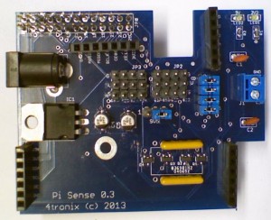
- For the correct holes, see the photo
- The writing needs to be to the top of the board (nearest the 4×3 connectors)
- Insert the 6-way and 8-way female headers, turn the board upside down to rest on the headers to keep them straight, then solder 1-pin only on each header
- Check that the headers are sitting straight. Adjust if necessary, then solder the rest of the pins
- Add in the 4x2and the 3×1 male header blocks. Again solder one pin on each, check it is sitting straight, then solder the remaining pins
- Solder the 2-pin connector if required
- Solder the L4940V regulator. Do this by putting it in vertically as far is it fits easily and solder it in this position. When soldered, simply bend it backwards into the position shown in the photo. Make sure the Red modification wire is still attached to the pin underneath
- Fit the DC Jack socket – big holes so lots of solder to keep it nice and sturdy
- Fit the GPIO socket. I know it’s obvious but fit this on the opposite side of the board to everything else!
How do I test it?
Carefully! We don’t want a blown Pi. I have been doing the following:
- Give it a careful check for solder shorts, stray bits of wire, etc
- Don’t connect the jumpers at this point
- Plug a battery pack (6.5V – 10V) into the DC jack socket and check the 5V LED comes on
- Remove the battery pack
- Plug the board, without external power, onto a Pi and power up the Pi (no need for an SD card at this stage), and check that both the 5V and 3V3 LEDs light up
- Check you have the correct voltages on the middle pins of the two 4×3 header blocks (3V3 on the left block and 5V on the right block)
How do I use it?
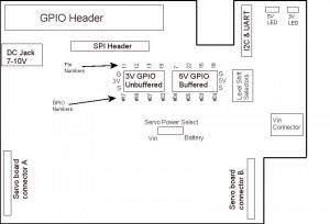
Use the rough sketch below to identify the locations of all headers. Due to the slight unexpected feature (bug), the silk screen is wrong for the 3-pin headers. The sketch below is correct:
- Pins on the GPIO socket numbered 11, 12, 13, 14 are brought directly on the header
- Pins 7, 22, 16, 18 are passed through 4 jumpers (level shift selectors) and then through the bidirectional level shifters . Leave all 4 jumpers in place if you want these 4 signals to be level shifted. Remove any jumper that you don’t want level shifting and you can use the exposed male header pin to access that signal, or use the opposite pin to feed any other signal through the level shifters. Is that clear? No, I thought not.
- On the SPI header, the 8th pin marked 5V on silk screen is not connected
- If you add in the PCA9685 board, you should build it with 2 male headers on the bottom of the board. Then it can be plugged directly into the female headers provided
- The “Servo power select” jumper allows you to select the power for the servos on the PCA9685 board. Vin is the direct power from the 2-pin screw terminal. “Battery” is actually the 5V line which is common for the Pi and the board. This is fine to use for small servos or perhaps 1 or 2 larger servos if the batteries are in use. Use the external screw terminal power if more or larger servos are in use
- Demos of board in use with a customer here: http://youtu.be/SKDD_sO2Rs4 and http://youtu.be/TS5DAGg9MJ4
Click to enlarge
How do I Get one then?
Well, first off, there’s only 5 available. We’ll allocate on a first come, first served basis.
Send an email with #FreePiStuff in the title, including your name and postal address, to sales@4tronix.co.uk


