Programming M.A.R.S. Rover in Microsoft Makecode

Makecode for 4tronix M.A.R.S. Rover

Installing the Extension

In the Makecode editor, select “Advanced” and then “Extensions”. Alternatively click on the gear icon and select “Extensions” from there

Then enter Rover or Mars Rover in the seach bar

Click on the extension and it will be loaded into your Makecode editor. You will now have a rocket ship icon, Rover, with several sub-sections

Calibrating the Servos

Before we start using the Rover we should calibrate the servos so that they run directly.

Load this project into your Makecode editor: https://makecode.microbit.org/_Mpt6xpCRF0EK by selecting “Import”, then “Import URL”

Alternatively, download it from https://4tronix.co.uk/rover/microbit-CalibrateServos.hex

This program goes round all the wheel servos and allows you to use the A and B buttons on the Microbit to set each servo to straight ahead position.

It indicates using the LEDs which servo is being calibrated.

When you are happy with each servo, press the A+B buttons together to store the setting and move onto the next servo. After setting all servos, simply switch off and start coding.

Drive:Bit Affordable Motor Controller for Microbit

Drive:Bit Motor Controller

Purchase Drive:Bit here

Drive:Bit has been created to provide a really affordable motor and robotics controller board for the BBC micro:bit. Even though we reduced the price as much as we could, we kept some great features which will make it an excellent board to build DIY buggies and the like

Connections

NB: Fit the Microbit into the connector with the LEDs on the Microbit facing the switch and indicator LED.

Connect your batteries to the 2-pin screw terminal, or the 2-pin header pins, on the left. The battery voltage should be in the range 6V to 10V, so use 4 x AA alkaline cells, or a 9V PP3 battery or similar. This input voltage is what is used to drive the motors and generate the 3.3V for the Microbit, so make sure that your motors can cope with the voltage you provide and that the voltage is kept high enough when the motors take a lot of current.

Connect your motors to the 2-pin screw terminals (or 2-pin male headers). Motor 1 is on the left, labelled M1. Motor 2 is on the right, labelled M2. The current to the motors is limited by the circuitry so it won’t damage the DriveBit if you try and take too much current. However, if things aren’t working, switch off and check for short circuits. Better safe than sorry!

In the centre of the DriveBit is a group of pins, 4 x 3. These are GVS (Ground, Voltage, Signal) pins that allow you to connect 3.3V devices (inputs or outputs) directly to the Microbit pins 0, 1, 2 and 8. Small, micro, servos such as SG90 can be plugged in directly – although they are 5V devices they will generally work at 3.3V.

Other pins are available on the top of the board as pads. You will have to solder wires in there, or you could add a (male or female) header yourself.

Programming Drive:Bit with Makecode

There is a Makecode extension available which makes it trivial to control the motors or set the status FireLed to any colour with or without flashing. The 4 GVS pins are general purpose so use other Makecode libraries to drive what you connect to these pins.

In Makecode editor go to Advanced and Extensions, then search for DriveBit

Driving Motors:

Setting the Status LED


Using Drive:Bit with MicroPython

For micro Python, you can drive the motors and the onboard status LED very simply. The pins used are:
Motor 1: Pin 12 and Pin 13
Motor 2: Pin 14 and Pin 15
LED: Pin 16

To drive forward, Set Pin 12 and Pin 14 to the speed you want, from 0 to 1023. And set Pin 13 and Pin 15 to 0. Eg. to drive at speed 600

pin12.write_analog (600)
pin13.write_analog (0)
pin14.write_analog (600)
pin15.write_analog (0)

To drive backwards, set Pin 12 and Pin 14 to zero, and set Pin 13 and Pin 15 to the speed you want, from 0 to 1023. eg to reverse at speed 600

pin12.write_analog (0)
pin13.write_analog (600)
pin14.write_analog (0)
pin15.write_analog (600)

To stop the motors, set both pins of each motor to 0. This will coast to a stop

pin12.write_analog (0)
pin13.write_analog (0)
pin14.write_analog (0)
pin15.write_analog (0)

To brake the motors quickly, set both to 1023

pin12.write_analog (1023)
pin13.write_analog (1023)
pin14.write_analog (1023)
pin15.write_analog (1023)

To drive the LED, you will need to import and use the neopixel library. This example sets the LED to Red

import neopixel
np = neopixel.NeoPixel(pin16, 1)
np[0] = (255, 0, 0)
np.show()

  • Line 1 imports the neopixel library
  • Line 2 sets up the array of LEDs that the library will use. We only have 1 LED
  • Line 3 sets element 0 (our only LED) to Red=255, Green=0, Blue=0
  • Line 4 copies the array of LED data to the LED itself


M.A.R.S. Rover Assembly

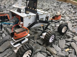
Assembly of 4tronix M.A.R.S. Rover Kit

Click on any photo to enlarge

The 4tronix Mars Rover is loosely based on the Curiosity and Mars 2020 rovers from NASA. It uses the same rocker arm, bogey and differential arm mechanism.

Purchase M.A.R.S. Rover from here

Coding for the M.A.R.S. Rover for Microbit in Makecode here

Coding for the M.A.R.S. Rover for Pi Zero in Python here

Some stats on the 4tronix Mars Rover

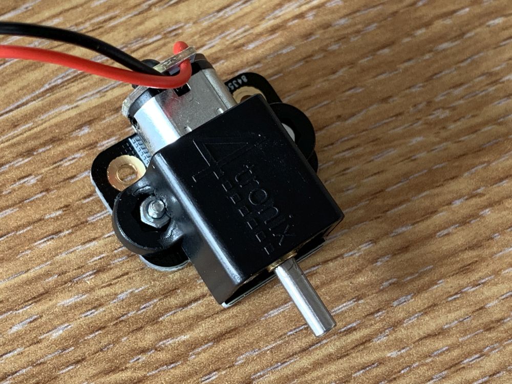
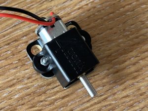
  • 6 Motors. 80 rpm 6V, N20 micro gear motors
  • 4 Servos. MG90S metal gear analog micro servos
  • Total number of special PCBs: 30
  • Number of different PCB designs: 11
  • Length: 200mm
  • Width: 185mm
  • Height without Mast and Microbit: 95mm
  • Height with Mast: 170mm
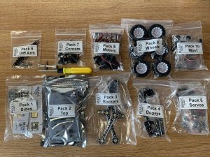
Kit Contents

NOTE: The kits for Raspberry Pi Zero and BBC Microbit are identical, except for the mainboards which are slightly different. The assembly guide is the same, whichever one you have. ALl photos are for the Microbit version.

The kit is packed in 10 bags, which should be assembled in order as follows

  1. Side pack. PCBs and screws to assemble both side pieces of the main body
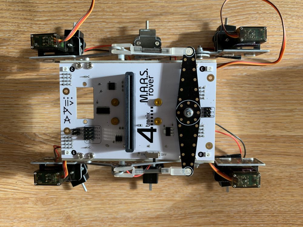
  2. Brains (Top) Pack. This PCB houses all the electronics and together with the side pieces (1) forms the structural body of the 4tronix Mars Rover
  3. Rocker Pack. These 2 rocker arms are pivoted on the screws fitted into each side piece. Each rocker arm carries a single servo for a front corner wheel assembly
  4. Bogey Pack. These two rear bogeys carry the centre and rear wheels for each side. The rear corner wheels are steered with a servo
  5. Servo Pack. This contains 4 metal gear micro servos together with screws to fix them into the Rockers and Bogeys
  6. Differential Arm Pack: The differential arm and couplers joins the two Rockers in such a way that it tries to keep the main body level (side to side) as one side or the other traverses uneven terrain. In earlier NASA Mars Rovers, this arm was replaced by a differential gear train, but the arm was found to be simpler and less prone to failures.
  7. Corner Wheels Pack. Each corner wheel is steered by its own servo. This pack contains the PCBs and screws needed to connect all four of the motor mounts to the servos
  8. Motors Pack. This includes the 6 motors, each ready-wired with a JST connector lead which plugs into the underneath of the main brains board. Plastic mounting brackets and associated screws are also included
  9. Wheels Pack: Six wheels. Just push them onto the motors. You must enusre that the D-shaped axle is aligned with the D-shaped hole in the wheel
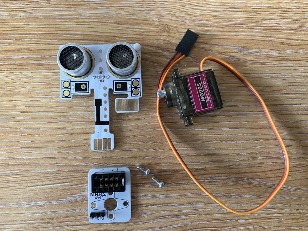
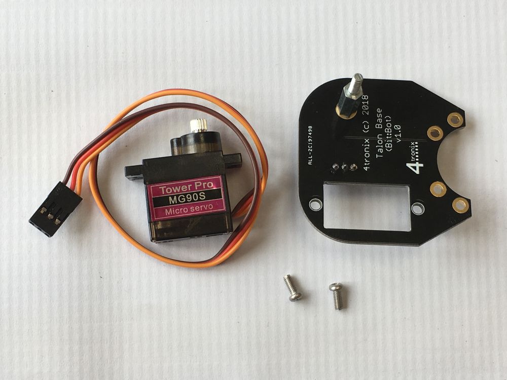
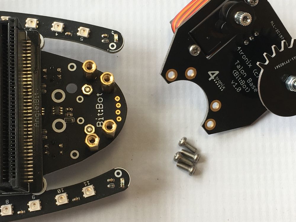
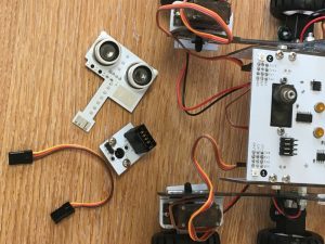
  10. Mast Pack. Includes another servo, the mast base and a plug-in mast head with an ultrasonic sensor and some LEDs.

Assembly

You should allow 2 hours to build this if you are used to assembling kits of this nature. If it is your first assembly of something like this, then you may have to double the expected timeframe.

Step 0

Check you have all the bags described above. There is also a spares bag, a spare servo, a screwdriver and a wrench. The screwdriver has both a flat blade and a philips blade end. Pull out the metal part and insert it the other way round to change ends.

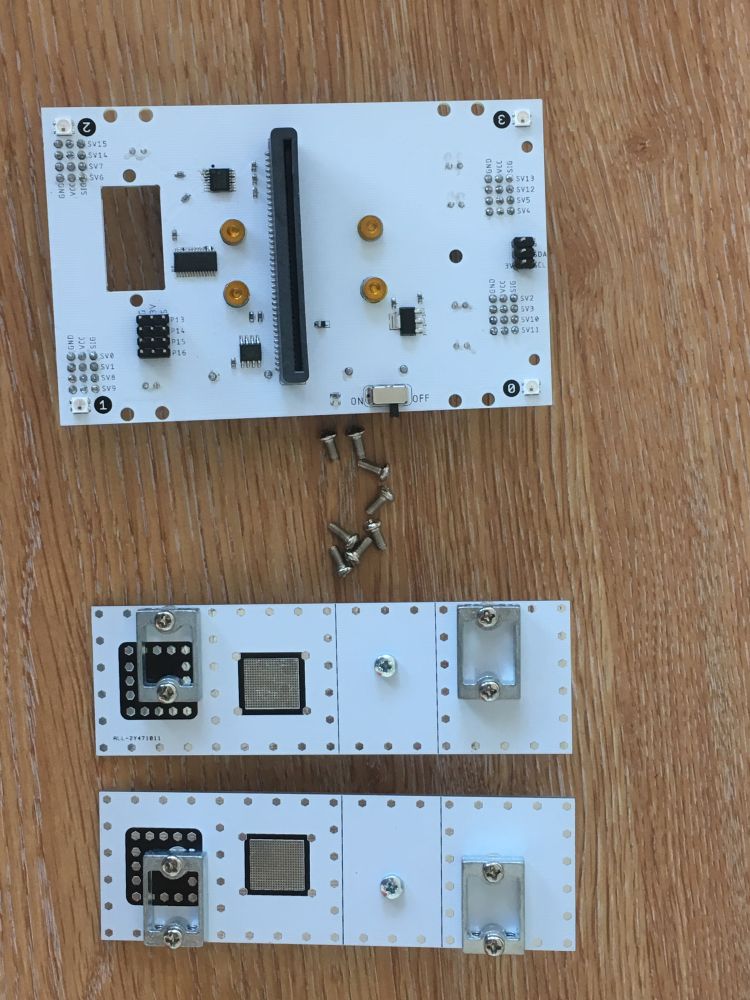
Step 1: Assemble the Sides

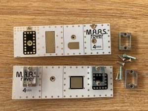
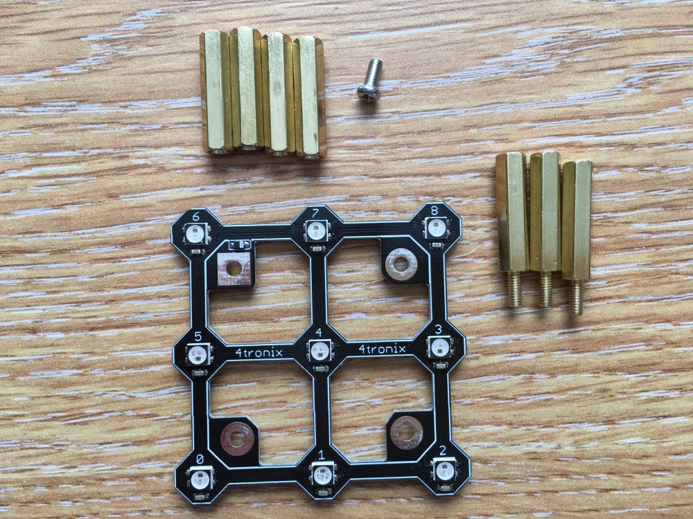
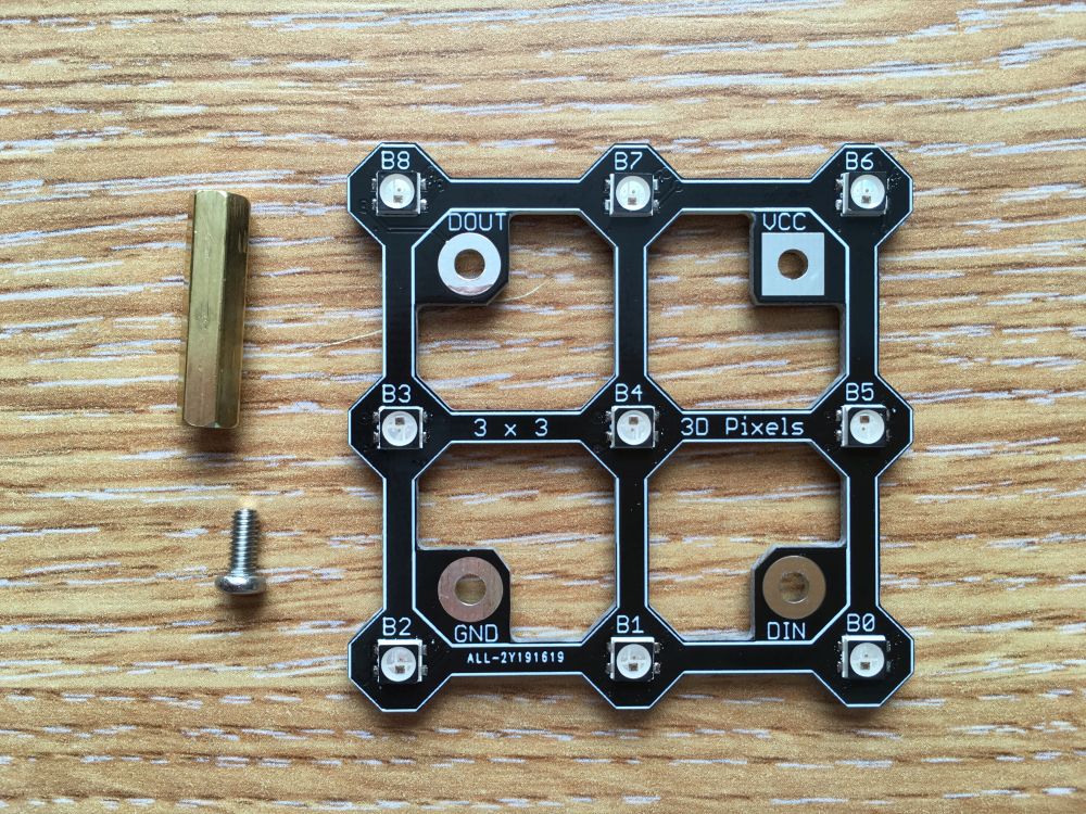
You should have two sides pieces (left and right), four aluminium brackets, eight 8mm M3 screws and two long 16mm M3 screws. Photo above shows 2 brackets fitted and two brackets ready to fit.

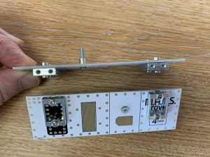
Screw the brackets into the side pieces from the inside as shown above. Make sure that the vertical screw holes in each brackets are next to the top surface of each side.

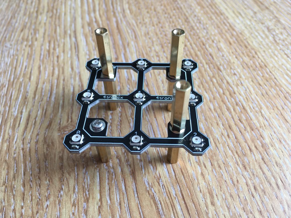
Then screw the long screw from the inside, through the PCB and through the fitted nut. Make sure all screws are tight as once it is assembled it will be very hard to get at them again

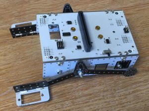
Step 2: Fit the Brains/Top to the Sides

You should have the Brains PCB and eight M3, 6mm screws (The Pi Zero version also has two M2.5, 6mm screws for fixing the Pi Zero to the pillars)

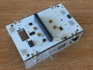
The sides should be fitted as shown above with the rocker mounting screw nearest the front (the end with the servo hole in the top/brains PCB)

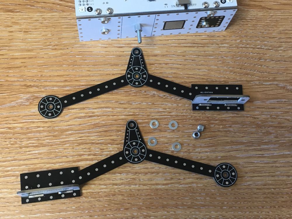
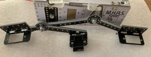
Step 3: Fit the Rocker Arms

You should have two rocker arms (left and right) with servo mounts fitted, two M3 nyloc nuts and 4 M3 washers

Place a washer onto the rocker pivot screw, then place the rocker arm, then a second washer and finally the M3 nyloc nut. Tighten up the nut (using the included multi-wrench) as far as it will go, then back it off the tiniest bit until the arm moves freely. If you loosen the nut too much the arm will wobble, so get it as tight as possible without binding.

The servo carrier on each side is at the front of the rover, facing outwards as shown above.

Step 4: Fit the Bogeys

You have two bogeys (left and right) with servo and motor carriers attached, two M3, 10mm screws, 4 washers and two nyloc nuts.

Fit the screw from the inside, through the rocker arm, then a washer, then the bogey, then a second washer and finally the nyloc nut. As with the rocker arms, do the nyloc nut up tightly then back it off slightly so the bogey moves freely. Again, it is much easier to use the screwdriver to hold the screw in place, then turn the multi-wrench to tighten the nut.

The bogeys also have the servo carriers facing outwards in each rear corner of the rover.

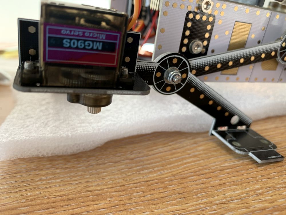
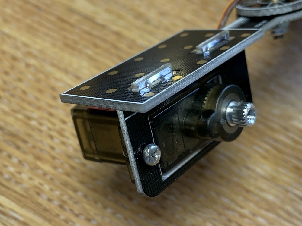
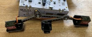
Step 5: Fit the Steering Servos

You have four servos and eight 6mm, M2.5 screws. You  may also have 8 nuts.

Mount each servo with the output shaft nearest the centre of the rover as shown above. Screw from underneath the servo mounting PCB into the holes on the side of each servo, as shown below. Depending on the exact model of servos you may also require the nuts to hold it tight. Keep hold of the servo arms and servo shaft screws, ready for Step 7.

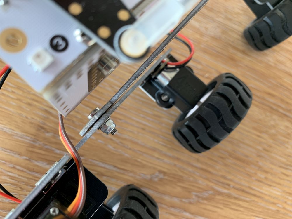
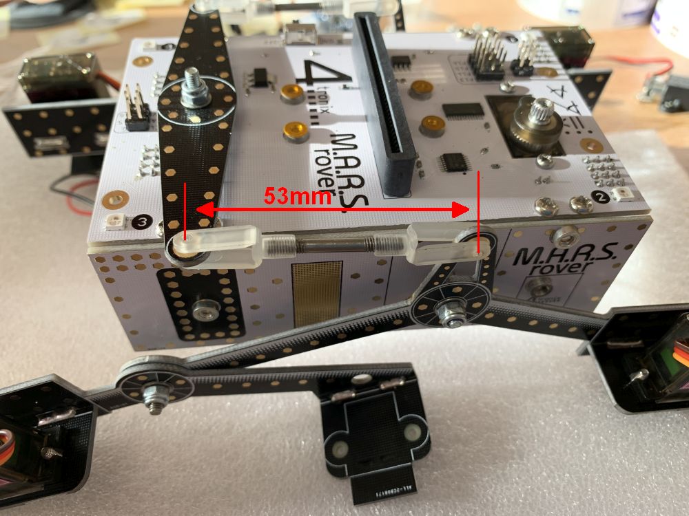
Step 6: Fit the Differential Arm

You should have the differential arm PCB, a long screw, 2 washers and a nyloc nut and 2 push-rods with 4 screw on snap links.

Screw the long screw from underneath, through the main board and into the fitted nut. Do up tightly.

Place a washer over the long screw and onto the fitted nut, then the differential arm, then the second washer and finally the nyloc nut. As with the rocker arms and bogeys, do up the nyloc nut tightly then slacken it off slightly

Finally adjust the pushrods and snap links by screwing in and out until the distance between the clip points is about 53mm. Then clip firmly into the top of each rocker arm and the ends of the differential arm.

When you have fitted the wheels (later) you can adjust the length of the pushrods to ensure that the body of the Rover sits level.

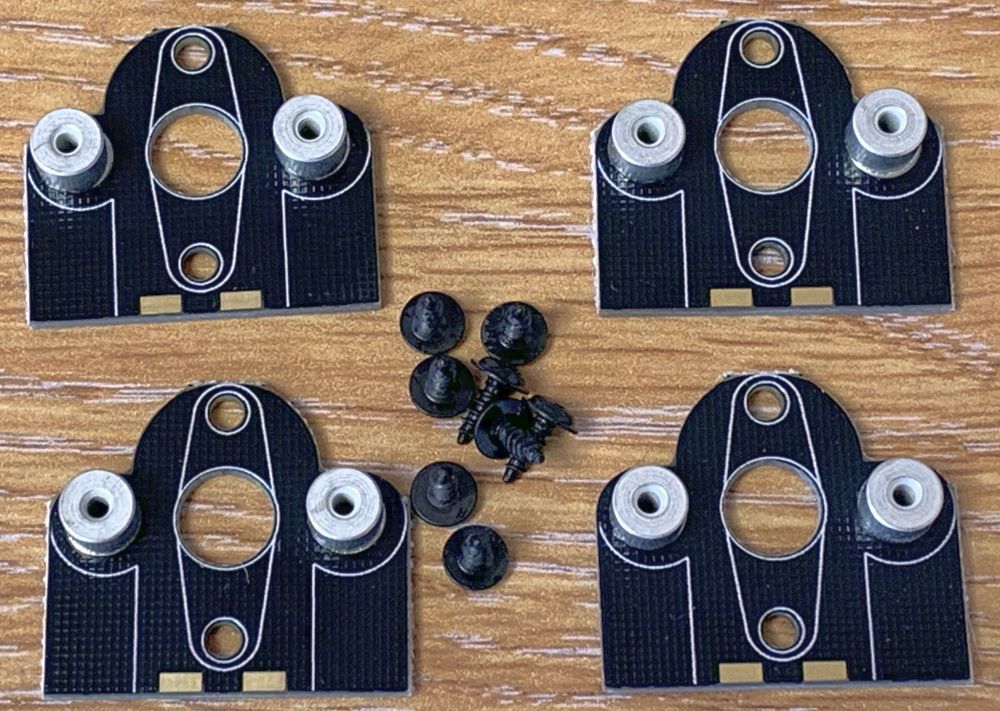
Step 7: Fit the Corner Wheel Mountings

You should have four top pieces with 4mm nuts attached and eight 6mm black screws.

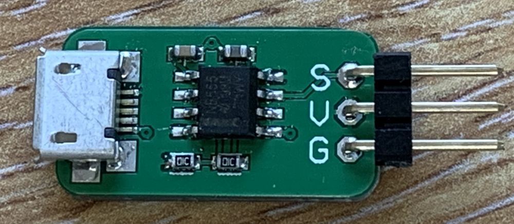
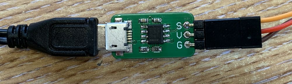
Also included is the Zero Servo – a little magic PCB that centres your servos without hassle.

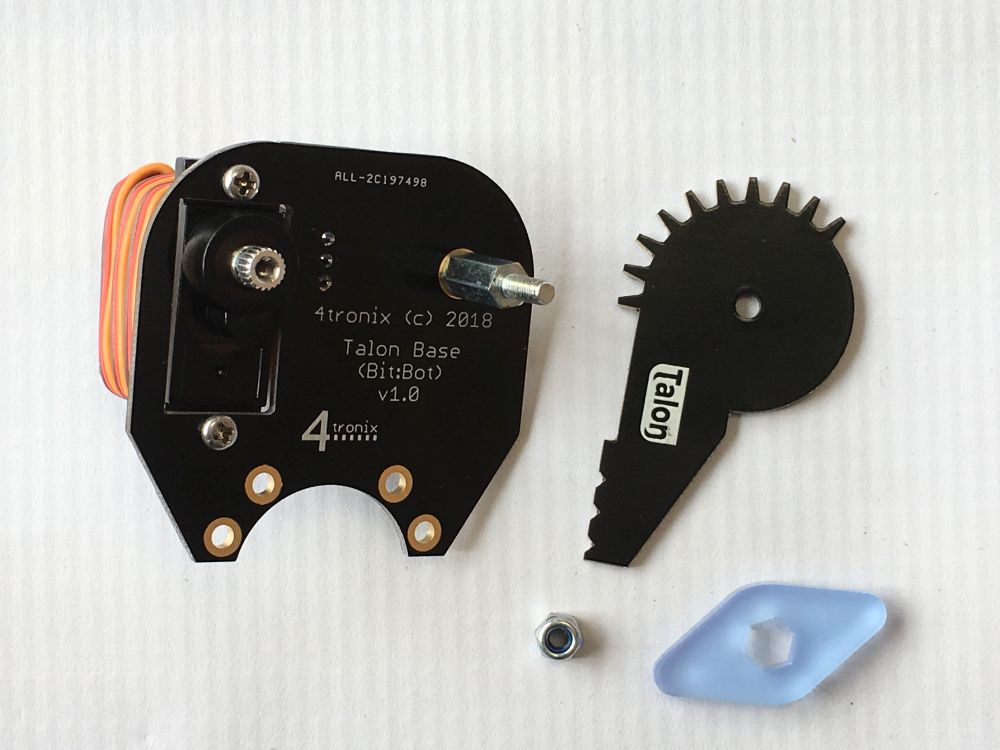
You will also need the four cross-shaped servo arms and servo shaft screws from the servo packs. Do not use the longer screws in the servo packs. If the soldered nuts still have the orange kaptan tape on, you will need to peel it off.

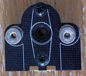
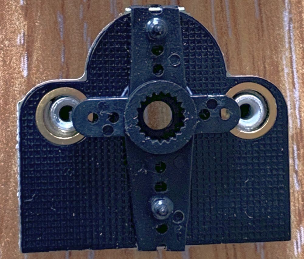
Fit the cross-shaped  servo arms to the top pieces with the nuts attached. The arms fit on the opposite side to the nuts and with the hole that accepts the servo shaft facing outwards. Note that the arms are not symmetrical – so the holes will only line  up properly one way round – the longer end goes towards the straight edge of the mounting PCB. You can use a pair of side-cutters (or nail clips?) to chop off the protruding ends of the servo arms.

IMPORTANT: it is important that the motors are mounted so they are pointing outwards at as close to 90 degrees as possible when the servos are set to 0 degrees.

Use a ServoZero (included) connected to power by a USB cable and plug each servo in turn into it to set to the zero position. We can fine tune the position later in software, but it is important to get it close mechanically.

After the the servos have been zeroed, then fit the motor mountings to the servo.

Use the little servo shaft screws from the servo packs to fit each motor mounting securely.

Step 8: Fit the Motors

You should have 6 motors with JST leads attached, 6 mounting brackets, 20 M2 screws and 12 M2 nuts. You will also have the 4 lower motor mount PCBs

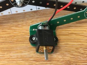
Mount the centre motors by fitting the nuts into the plastic brackets, then screwing through from underneath into the nuts. See photo above.

The corner motors are mounted by first fitting them to the lower motor PCBs from Pack 7 using 2 screws and 2 nuts for each.

Then screw the resulting assembly onto the 2 fitted 4mm nuts on the PCBs you assembled in step 7.

With all six motors fitted, attach the JST leads to the connectors underneath the main board. It doesn’t matter which connector you use as long as the left side connects to left motors and the right side connects to right motors.

You can use this opportunity to connect all the servo leads as well. These need to be connected to the servo connector nearest to them. So use 9, 11, 13 and 15.

You can wrap the spare lead around the servos to tidy the cables up a little. An alternative method that I use is to put the cables down the side of the battery holders underneath and hold them in with a peice of foam cut from the packing in the box.

Step 9: Fit the Wheels

The six wheels simply push on, but be careful to line up the D-shaped hole in the wheels with the D-shaped axle. Only push the wheel when holding the motor, not when hold the body.

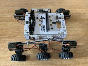
It looks better (I think) if the wheels are on “backwards” with the spokes showing

Step 10: Fit the Mast

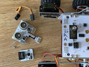
The mast houses an ultrasonic distance sensor and 2 White LEDs (not controllable). It is fitted onto a steerable servo and can be removed simply by unplugging it.

This pack contains the servo, the mast base PCB, the mast head PCB, two M2.5 screws to secure the servo and 4 short self-tapping screws to secure the servo horn to the mast base.

NB. Pi Zero version also includes two M2, 4mm screws to attach a standard Raspberry Pi camera (not included) to the Mast Head.

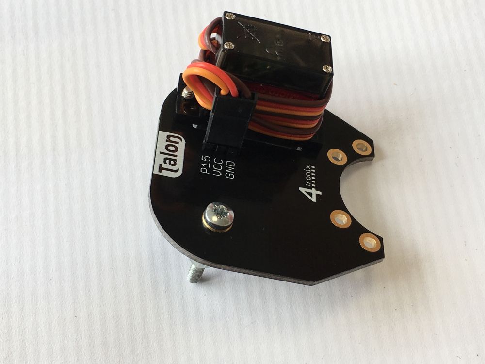
Fit the servo by screwing the M2.5 screws through the top PCB into the holes on the side of the servo. Connect the servo lead to position SV0 underneath.

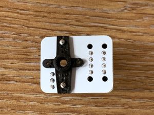
Fit the cross-shaped servo horn from the servo bag to the bottom of the mast base PCB using the 4 small self tapping screws.

Fit it so that the connector is pointing forwards when the servo is at its centre position. Use the small shaft mounting screw in the servo bag to fix it firmly to the top of the servo shaft.

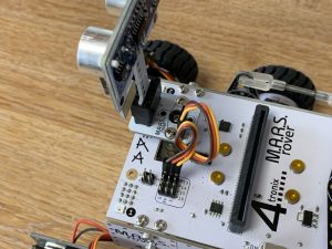
Then plug in the mast head and plug the 3-wire lead from the mast base to position P13 for Microbit (#23 for Pi Zero) on the top of the main board. Ensure the Brown wire is next to G on both boards.

Step 11: Fit the Microbit or Pi Zero

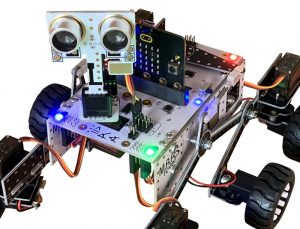
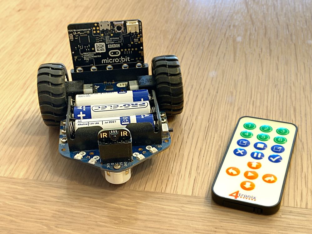
The Microbit should be plugged in with the LEDs facing forwards as shown above.

The Pi Zero (with header) should be plugged in facing downwards and to the rear of the Rover as shown above

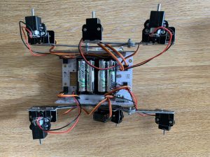
Step 12: Fit the Batteries

You will need 4 x good quality rechargeable AA batteries. It is possible to use with alkaline batteries, but only when they are fresh. This applies particularly to the Pi Zero version, which requires additional current during booting that can only be supplied by rechargeable batteries. We recommend Eneloop or Energizer Extreme.
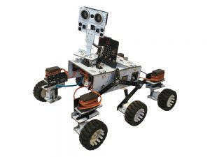
Complete!

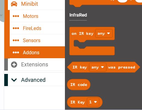
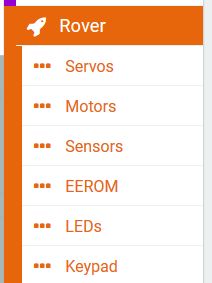
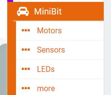
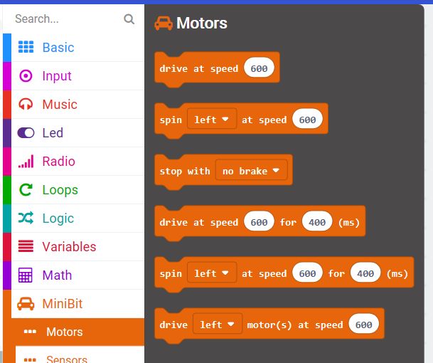
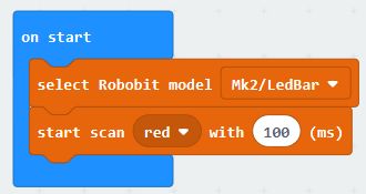
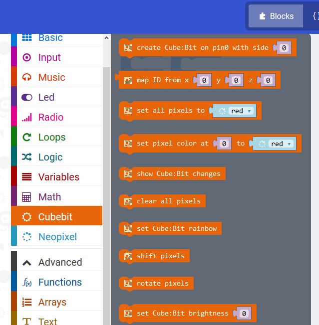
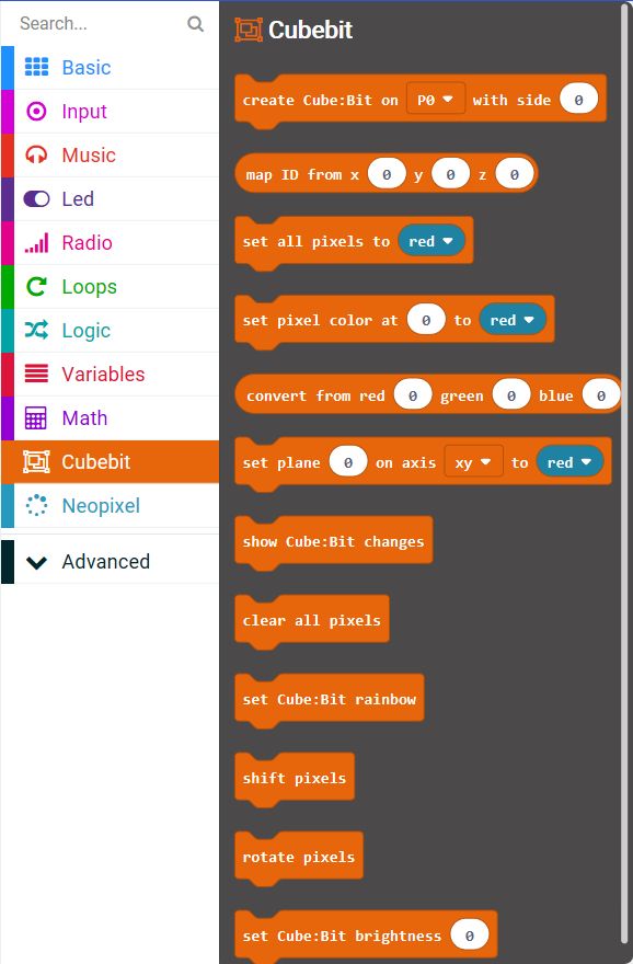
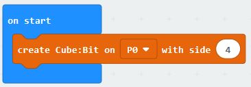
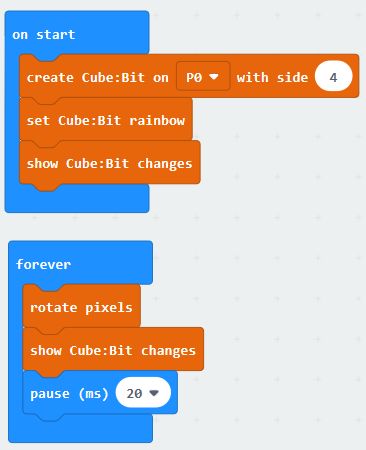
Now for some coding using Microsoft Makecode: Makecode extension is from https://github.com/4tronix/MARS-Rover

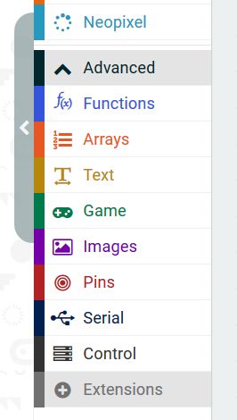
In Makecode, click on Advanced, then Extensions. Enter the URL above into the search bar. See this guide.

For Pi Zero and Python, see this guide.

MiniBit

MiniBit Entry-Level Robot for Microbit

Purchase here

Overview

MiniBit is a ready-assembled simple and inexpensive robot for the BBC micro:bit.

It has the following features:

  • Ready-assembled. Just push on the wheels
  • Edge connector to easily insert the Microbit
  • Micro metal gear motors with fully-enclosed gearbox (no grit or fluff can enter)
  • Wire-free battery holder for 3 x AA batteries
  • 4 x Smart RGB LEDs (neopixel compatible)
  • Integrated Pen holder for 10mm diameter pens (eg. Sharpie felt tips)
  • Robust On/Off switch with Blue indicator LED
  • Wide chunky wheels with lots of grip
  • Metal ball front caster
  • Connector for optional ultrasonic sensor or I2C breakouts (fully compatible with Pimoroni’s Breakout Garden range)
  • The Microbit pins 0, 1, 2, Gnd and 3V are available for use with croc clips etc.
  • Lots of mounting holes to create your own “body” for the robot or additional sensors etc.
  • Makecode extension and micropython examples available

Batteries

Please use Alkaline batteries. Rechargeable batteries do not provide sufficient voltage once they have started to deplete. This primarily affects the ultrasonic sensor, so you may be okay to use with the other functions even when the batteries get low

Coding Your MiniBit

Calibrating the Motors (v1.3 or later Only)

For version 1.3 of Minibit we have added code and hardware to help calibrate the motors on either side so that they match speeds better. Once the motors are calibrated, the calibration values are permanently remembered on the Minibit, so even using different Microbits and different programs, you will still get the matched motors. For this to work you must use the latest Minibit Makecode extension.

The calibration Makecode program can be downloaded from >here<. Load it into your Makecode editor and download to the Microbit on the Minibit v1.3 or later.

Process: The calibration program starts at speed 30 (displaying 3 on the Microbit LEDs). You then set the left or right speeds until it is driving straight. Then give the Minibit a good shake and it will change to speed 60 (displaying 6). Set this speed, shake again to change to speed 90 (displaying 9). Once this speed is set correctly, shake again and it will return to speed 30. You can then switch off and all the values are stored. If you run the program again, you will start from the un-calibrated values and must follow all the steps again.

  • Load the program into the Microbit and plug it into the Minibit
  • Switch on the Minibit. It will display 13 (indicating a v1.3 Minibit), then change to show 3 (meaning speed 30)
  • Press A or B buttons to affect the turning left or right, then press both A+B simultaneously and the Microbit will display the current calibration value, then move forward for 2 seconds at speed 30.
  • If it is still not moving straight, press the appropriate button one or more times to straighten it up, then press A+B again to test it
  • When you’re happy that it is moving straight, give the Minibit a shake and it will store the values for speed 30 and move onto Speed 60.
  • Repeat for speed 60 and speed 90

Microsoft MakeCode

Click any image to enlarge.

To load the extension, select Advanced, then Extensions. Then enter “Minibit” into the search box and press Enter. If that doesn’t find it (there are sometimes earch glitches) you can enter the full URL into the search box: “https://github.com/4tronix/MiniBit”

NB. This post is being updated to relate to the new functions added (Feb 2020). Images may not match the text.

Once loaded, you will have a MiniBit menu item with 4 sub-folders: Motors, FireLeds, Sensors, Addons

Motor Blocks

The “New style block” section contains command for basic movements eg. “Go Forwards/Reverse at speed 60” or “Rotate Left/Right at speed 40 for 700 ms”. All the commands in this section use speeds from 0 to 100 inclusive.

Both the “Go” and the “Rotate” blocks have a paired block that will do the command for a selected amount of time and then stop

There are two ways of stopping. Coasting to a stop or braking. If you set the speed to 0 or use the “stop with no brake” command, then it will stop gently over the coourse of a second or so depending on initial speed). If you use the “stop with brake” block (or the go/rotate for a time block) then it will stop almost immediately.

You can also drive each motor individually using the “Move Left/Right/Both motors…” block. For instance if you set the left motor to drive at 600 and the right motor to drive at 1000, then it will perform an arc towards the left

We have introduced a new command to bias the driving in one direction or the other. This is to counteract any mismatch between the motors. So if your robot drifts over the left when you want it to go straight, then add a bias to the Right. At a speed of 60, a bias of 10% is roughly equal to 10 cms or so.

FireLed Blocks

You can use these blocks to set and clear one or all the FireLeds.

Using the “Enable Bluetooth” block at the top level you can disable the Fireleds. The Bluetooth software for Microbit is not compatible with Fireleds (like neopixels and all such LEDs) so you should switch off the Fireleds using this block if you want to use the Microbit Bluetooth functionality.

Note that the MiniBit defaults to automatically updating the FireLeds whenever any change is made, but you can change this behaviour by setting the update mode to manual. Then you would have to run the “Show LED changes” block after making any changes to the LED settings.

The LEDs on the MiniBit are labelled from 0 to 3. Use these numbers in the Makecode blocks to change the colour. eg setting LED 1 to Purple could be done like this:

The default brightness level is 40. This is plenty bright enough for most uses, saves damaging eyes, and reduces battery consumption. If required you can change the brightness from 0 up to 255

In the Advanced section of FireLeds :

Set update mode is used to switch between automatic LED updates or manual LED updates. The default is for automatic updates: every change to the LEDs results in all the LEDs being written to with the updated values. This is easy to understand, but it does mean that when making a lot of changes it can slow things down considerably. If doing that, it is best to use Manual update mode, make all the changes required, then use the show LED changes block to make all the updates in one go.

Rotate LEDs block will move the colour in LED 0 to LED 1, LED1 to LED2, LED2 to LED3 and LED3 to LED0. If done repeatedly, with a delay between each one, it will show the LED colours rotating around all the 4 LEDs.

Shift LEDs block will move LED0 to LED1, LED1 to LED2 and LED2 to LED3. It will blank LED0. So all the colours will disappear one at a time from 0 to 3

You can also create your own colours and replace the fixed list of colours in any command using the convert from red, green, blue block. For example, to set LED0 to a blue-green colour:

Sensor Blocks

Ultrasonic distance sensor: You can get the values to the nearest object in cm, inches or microseconds. This block returns a number that you can put into a variable or use it directly in a calculation or test

Line sensors: This optional accessory has 3 sensors: left, centre and right. These are connected directly to Pin 0, 1 and 2 of the Microbit. There are two ways of using the sensors: a) read the current value and check it’s state before deciding what to do, or b) use a block that only gets run when the requested event occurs. eg: when the left sensor finds a (black) line

More Blocks

These are the advanced usage blocks. Most students will not need to use them.

  • Set update mode is used to switch between automatic LED updates or manual LED updates. The default is for automatic updates: every change to the LEDs results in all the LEDs being written to with the updated values. This is easy to understand, but it does mean that when making a lot of changes it can slow things down considerably. If doing that, it is best to use Manual update mode, make all the changes required, then use the show LED changes block to make all the updates in one go.
  • Rotate LEDs block will move the colour in LED 0 to LED 1, LED1 to LED2, LED2 to LED3 and LED3 to LED0. If done repeatedly, with a delay between each one, it will show the lED colours rotating around all the 4 LEDs.
  • Shift LEDs block will move LED0 to LED1, LED1 to LED2 and LED2 to LED3. It will blank LED0. So all the colours will disappear one at a time from 0 to 3
  • You can also create your own colours and replace the fixed list of colours in any command using the convert from red, green, blue block. For example, to set LED0 to a blue-green colour:

Programming in microPython

Driving Motors

The motors use 2 pins each to determine the speed and direction. In microPython we use write_analog ( ) to set the first pin to a value between 0 and 1023 and the second pin to 0 in order to go forward. To reverse, we swap the pins so that the first pin is set to 0 and the second pin is set to the value.

On the MiniBit the left motor uses pins 12 and 8, and the right motor uses pins 16 and 14.

So to move the left motor forwards at speed 600:

pin12.write_analog(600)
pin8.write_digital(0)

And to move the right motor in reverse at speed 450:

pin16.write_digital(0)
pin14.write_analog(450)

To stop with no brake, use write_digital ( ) to set both pins to 0. To stop with brake, set both pins to 1.
eg. stop left motor with coasting and right motor with brake:

pin12.write_digital(0)
pin8.write_digital(0)

pin16.write_digital(1)
pin14.write_digital(1)

So a complete, but fairly useless, program to drive the motors for 2 seconds and then stop quickly, would look like this:

from microbit import *
pin12.write_analog(600)
pin8.write_digital(0)
pin16.write_analog(600)
pin14.write_digital(0)
sleep(2000)
pin12.write_analog(0) # temporary fix for python bug
pin12.write_digital(1)

pin8.write_digital(1)
pin16.write_analog(0) # temporary fix for python bug
pin16.write_digital(1)

pin14.write_digital(1)

Note the 2 lines that write_analog(0) before swapping a pin from analog to digital. These are required until a fix is obtained for the python PWM driver continually updating the pin type to analog

Lighting the LEDs

This uses the standard neopixel code, with the LEDs connected to Pin 13.

At the top of your program add import neopixel then:

leds = neopixel.NeoPixel(13, 4)

leds is then an array of all 4 LEDs. leds[0] refers to the LED 0 and leds[3] refers to LED3. Each element of the array is a set of 3 numbers representing the Red, Green and Blue values (each 0..255) for that LED. So to set LED2 to Blue:

leds[2] = (0, 0, 255)

All this does is update the array. To show the new value of the array, we need to call the show ( ) function as follows:

leds.show ( )

Reading the Ultrasonic Distance Sensor

The ultrasonic sensor breakout is on pin15.

The concept is simple: send an ultrasonic pulse out, then time how long it takes to return. Using the speed of sound and some maths, we can then work out the distance. The following complete program has 2 parts to it: a function sonar ( ) which returns the distance to the object, and the main code in a loop which continually prints the distance. We also need to import the utime library:

from microbit import *
from utime import ticks_us, sleep_us

def sonar():
    pin15.write_digital(1) # Send 10us Ping pulse
    sleep_us(10)
    pin15.write_digital(0)
    while pin15.read_digital() == 0: # ensure Ping pulse has cleared
        pass
    start = ticks_us() # define starting time
    while pin15.read_digital() == 1: # wait for Echo pulse to return
        pass
    end = ticks_us() # define ending time
    echo = end-start
    distance = int(0.01715 * echo) # Calculate cm distance
    return distance

while True:
    display.scroll(sonar())
    sleep(1000)

Programming Robobit Buggy in Makecode

Programming Robobit Buggy

The Microbit Makecode Package supports all versions of the Robobit. Go to https://makecode.microbit.org/ or download the PC app from here 

Select Advanced or click on the gear icon, then select Extensions. Enter Robobit in the search box and search.

After it has loaded you will have an extra tool in 4tronix Orange with the Taxi icon, called Robobit

If you click on the Robobit tool, there are 3 subfolders for the Motors, the Sensors and the LedBar. There is also a single top-level block to allow you to select your model of Robobit – this should be used at the very start as shown below. In fact it can be the only thing in the start block

Now you are ready to start programming…

Programming the Motors

It’s a robot – you want it to move. So let’s see what we need to do.

The motors are individually controllable. So if you want, you can set different speeds for the left and right motors. But to start simply, let’s just drive forwards and backwards.

Forwards is represented by speeds from 0 to 1023. Backwards is speeds from -1023 to 0.

In both cases, 1023 is the fastest and 0 is dead stop. You will find that speeds below 200-300 may not be able to move the robot very much (it depends on battery levels, how “free” the motors are, etc)

The following code simple drives forwards at speed 600 (both motors at the same speed) for 1 second, stops for a second, then reverses and stops again. It repeats this forever

Yes, we have a moving robot!

NB. You may find, especially when the motors are new, that they go at different speeds and it doesn’t travel in straight lines. This is normal. The motors have a 10% speed tolerance, so can always be different speeds, but when they are new they can be especially stiff and even more different. Run the motors at full spoeed for a few minutes to free them up.


More Complex Motor Control

We can try and move in a square, or other shape. Great if you’re on a piece of paper and using the pen (Pen holders are designed for Sharpie felt tip pens – other pens are available)

Drive forwards for a bit, turn for a bit and do this 4 times. If you get the speed and times correct then a square can be formed. You will have to experiment with the speeds and times

The code above (click to enlarge) will do a four-sided figure and then stop. You will have to adjust the timings and/or speed of the spin to get it to accurately draw a square.

Of course, this software is tedious. It does the same thing 4 times. It would be better to use a loop function like this:

Here, we are using the “repeat nn times” block from the “Loops” toolbox


Now Let’s Flash some LEDs

It’s always fun to light LEDs and especially fun if you can control them individually with different brightness and colours.

The Robobit Mk3 and the Mk2 with LedBar have a row of 6 LEDs across the front as well as one in each front corner for a total of 8.

Scanner Feature

The Makecode package has a unique “Larsson Scanner” feature built-in which enables you to very easily scan the centre 6 LEDs back and forth at your choice speed and colour. Let’s do this to start with:

From the LedBar section of Robobit, select the “start scan…” block and insert it into the program after setting the required Robobit model. Here we are using a Mk2 Robobit with a LedBar attachment.

This code will immediately start the centre 6 LEDs scanning using various intensities of Red, with a delay of 100ms between changes, just like the Knight Rider KITT car!

Standard LED Programming

Normally when using the LEDs you will set on or more LEDs to a particular colour depending what you want the program to display. To do this, you need to understand how to work with individualy LEDs.

There are blocks you can use to set individual LEDs (or pixels), or all the LEDs at the same time. You can select colours using the names of colours (eg. Red, Yellow, Green, etc) or you can specify your own colour in terms of Red, Green and Blue components. All these blocks set the memory in the Microbit for the LEDs, but they do NOT update the LEDs with this memory information. To do that, you must use the most important block of all:

After doing this, all the changes you have made will be shown on the LEDs.

The other thing to remember is that the 8 LEDs are numbered from the left at 0 to the right at 7. So to flash the leftmost LED in Orange, we could do this:

This will set the LED at position 0 to orange, then wait for half a second, then set the LED to black (this is the same as OFF), then wait another half a second. Then this keeps repeating forever. Notice that each time we update the LED information, we than “show the LedBar changes”.


Using Sensors

Depending on your Robobit model and options fitted you may have an Ultrasonic Distance sensor and/or line following sensors. For the Robobit Mk3, these are both included as standard. For the Mk2, they can be purchased as options.

The Robobit Makecode extension includes blocks for using these easily.

Line Following Sensors

There are 2 of these mounted underneath the buggy, close to the front caster. They both use the same hardware sensor (TCRT5000) but the integrated ones on the Mk3 use 4tronix electronics specifically designed for this application whereas the Mk2 uses generic modules which have a trimmer on. Turn this until the LED turns off when it goes over a black line. You will find that the integrated units perform better.

The key thing to remember is that the Robobit buggy and the motors have a lot of interia when moving and cannot stop very quickly, so you must design your line follower program to move slowly (there are clever things that can be done, but we won’t look at that now). The Mk2 will have to go slower than the Mk3 because of the difference in sensitivity of the sensors.

To create a track to follow, you can use black electrical tape, or a permanent black marker. The surface needs to be reflective and the tape or marker pen needs to be not reflective. I prefer to print the tracks using track tiles from RobotSquare as these work excellently.

The simplest algorithm will be to check each sensor. If it is over a line, then turn the buggy that way, otherwise carry straight on. Keep checking in a loop like this:

Note that we are using speeds of less than 400. For a Mk1 or Mk2 you will probably have to go even slower.

This is a very basic algorithm and will have problems with junctions on the track etc. it also won’t do very well in a speed trial.


Ultrasonic Distance Sensor

These little sensors work like bats, by sending out an ultrasound ping and waiting for the echo to come back. The time for the echo to come back, together with the speed of sound, gives us an idea of the distance. Do not expect ultimate accuracy from these sensors.

You can choose to get the distance back in different units: centimetres, inches or microseconds. These examples all use centimetres (cm).

Obstacle Avoider

This simple program drives forwards until it detects an obstacle, then spins and reverse to avoid it before setting off again.

The first block checks if the robot is within 20cm of an object. If it is then it reverses at speed 500 for half a second, before turning left for 400ms. If it is not less than 20cm from an object it just drives straight on at speed 600.


Follow Me Program

This fun little program drives forwards until it gets close to an object and then stops. Then if the object (eg. your leg) gets further away, it will start moving again to follow you. However, if your leg gets closer then it will back away trying to keep the same distance from you:

In this one, we have created a variable called Distance so that we can check it against 2 values without reading the sensor again. Here we reverse the robot if it less than 20cm away and go forwards if it is more than 30cm away. Between 20cm and 30cm the robot will stay still.

Robobit Buggy Mk3

Assembling and Using Robobit Mk3

Robobit Mk3 buggy is a fully integrated and updated version of the Mk2 with all options (except Talon grabber) ready integrated into the unit

Purchase Robobit Mk3 here

Features

  • Compact design DIY robot that is easy and quick to build
  • No soldering required. Screwdriver and spanner widget included and are the only tools required
  • Presented in an attractive gift box
  • Integrated ultrasonic distance sensor
  • Integrated line follower sensors
  • Integrated pen holder (designed for Sharpies, but other pens will fit)
  • Integrated RGB smart LEDs (aka neopixels) with semi-automatic Larsson scanner function
  • Fully supported by the Microsoft Makecode extension – search extensions for “Robobit”
  • Powered by 4 x AA batteries (not included)

Assembly

Step 1 – Check you Have the Correct Parts

IMG_2444a

  • Main PCBA with prefitted ultrasonic sensor
  • Battery Holder PCBA (NB. Ring fits to rear of robot – no matter what it says on it!)
  • 2 x bags with motor mountings
  • Bag with 4 x 6mm M2.5 screws and 2 x 25mm pillars (6 screws on v1.2 and earlier)
  • 2 x motors with pre-fitted cables and plugs
  • 2 x Wheels

You should also have 2 tools: a double ended screwdriver (pull out of handle and turn round ot get alternate end), and a Pimoroni “spanner widget” for the motor mount nuts


Step 2 – Fit the motor brackets to the Motors

IMG_2445a

Mount the brackets the opposite way to each other so you have left hand and right hand assmblies as shown.

Use the Pimoroni spanner widget to held the nuts while you tighten the screws.

NB. Very important to ensure the edges of the nuts are flat with the top of the motors or the motors will be at a strange angle when fitted.


Step 3 – Fit Motors to Mainboard

IMG_2446a

Use the two 8mm M3 screws in each motor mount bag to fit the motors to the top of the main PCBA as shown above. Do these up tightly so the motors do not come loose with use.

Ensure the axles are at the rear and facing outwards.

IMG_2447a

Tighten the screws fully


Step 4 – Fit the Front Caster (v1.2 and earlier only)

IMG_2448a

Remove the ball if it is supplied already in the housing

Use two of the 6mm screws to fit the housing the the bottom of the main board as shown above


Step 5 – Fit the Battery Mounting Pillars

IMG_2449a

Use two of the 6mm screws to fit the 25mm pillars as shown above

Tighten up fully


Step 6 – Attach the Battery Holder

IMG_2450a

Use the remaining two 6mm screws to attach the battery holder firmly

Ensure the pen holder ring of the battery holder is directly above the pen holder hole in the main board


Step 7 – Finish

Push on the wheels and pop in the caster ball

Fit batteries.

Add your Micro:Bit and start programming!

Visit Programming Robobit Buggy in Makecode

Programming in Python

For text-based programming there is micro-python, and I prefer to use this offline using the Mu editor.  It provides a very neat and easy way of interfacing to the micro:bit without all the fuss of dragging and dropping.

Note on examples: We want to show people how the various features can be used. We don’t want to do the coding for you – that is the learning experience you should be taking away from using it. In the following examples, we will give you the tools to use all the features of Bit:Bot but it is up to you to combine them together in your code to make it do something useful. We do give a complete example of line-following – but it is a very basic algorithm and will get confused at T-junctions  and crossings; and it doesn’t use the neopixels.

Some great tutorials/examples for BitBot (which is very similar) by Mark Atkinson here

Motors

Each motor has two pins connected to it. One determines the speed and the other the direction:

Left motor: Speed Pin 0, Direction, Pin 8

Right motor: Speed Pin 1, Direction Pin 12

The simplest way to make the motors move is to set the Speed pin to HIGH and the Direction pin to LOW (to move full speed forwards)

Move left motor Forwards:

pin0.write_digital(1)
pin8.write_digital(0)

Move left motor Reverse:

pin0.write_digital(0)
pin8.write_digital(1)

If we want to change the speed of a motor, so that it is not going at full speed all the time, we need to use PWM (Pulse Width Modulation). This is means of changing the amount of power given to the motor by switching it on and off very fast. The percentage value of PWM determines the amount of each cycle that the output is ON. So a percentage of 100% is the same as being on all the time and thus the same as the examples above. A percentage of 50% would mean that the motor is only energised half the time, so it will go much slower. Note that the actual speed of the motor is not the same as the percentage of PWM – the motor won’t turn at all if the PWM value is too low and you will also get some stuttering at certain values. Nevertheless, being able to change the speed makes for a much better robot. For example, you can make a line follower that smoothly follows the line, rather than the normal shaking left and right.

To change the PWM value of a pin, we must use the analog_write commands. These can be set to a value between 0 (always off) to 1023 (always on), so 50% would be 511. Here are the commands to change the speed of the Right motor to approx 75% (value is 770)

Move right motor forwards at 75%

pin1.write_analog(770)
pin12.write_digital(0)

Doing this for the motors moving in reverse is a little confusing. Remember we need to change the direction pin to 1 for reverse. Then we need to set the amount of time in each cycle that the speed pin is LOW. This is the opposite of moving forwards, where we set the time for it to be High. Se we simply take the number (770 in this case) away from 1023, giving 253:

Move right motor Reverse at 75%

pin1.write_analog(253)
pin12.write_digital(1)


Neopixels

In fact, the name “neopixel” is a termed coined by Adafruit, but like “hoover” was a name of a brand of vacuum cleaner and is now a general term for all similar products, whoever makes it. The generic term is “smart RGB pixel” and is usually referenced with the name of the chip WS2812B. However, there are many different chips, all performing in a compatible way. The ones on the Robobit Buggy Mk3 are actually SK6812-3535

These smart RGB pixels are able to display any of 16 million colours by selecting a value of 0 to 255 for each of the Red, Green and Blue LEDs on each chip. The whole thing is controlled by a single pin on the BBC micro:bit (pin 13 for Robobit Buggy Mk3). It is simple to use the included neopixel libraries to control each pixel individually.

The 8 pixels are labelled on the Robobit Buggy Mk3, from 0 on the left arm to 7 on the right.

Set neopixel 2 to purple (red and blue)

import neopixel
np = neopixel.NeoPixel(pin13, 12)
np[2] = (40, 0, 40)
np.show( )

The first line imports the neopixel library. We only need to do this once, at the very top of your Python programThe second line creates an Python list with an element for each pixel. As shown, it specifies 12 pixels connected to pin 13. If you added more neopixels then you would increase the number from 12 by the number of pixels you added. eg. if you added a McRoboFace, then the total would be 12 + 17 = 29 so you would change the line to: np = neopixel.NeoPixel(pin13, 29)
The third line sets the pixel we have selected (number 2 in this case) to the colour which is set by three values in the brackets, each value can be from 0 to 255 and covers Red, Green and Blue. In our example we have set Red and Blue to 40.
The fourth line tells the neopixel library to copy all the data to the neopixels, from the Python list that we have been working with. It is only at this point that the LEDs change. In general, you would make all the changes you want and only at the end would you use a np.show( )

Line Follower Sensors

These are digital inputs and connected to Pin 16 (left) and Pin 14 (right).

You can use digital_read commands (as shown below) to read the value of each sensor. If the left sensor detects a line, it means the Robobit Buggy Mk3 is too far to the right, so it should move left. The opposite is the case if the right sensor detects a line. Here is some simple code for line following in Python (the actual motor commands are in separate functions for clarity)

while True:
    lline = pin16.read_digital()
    rline = pin14.read_digital()
    if (lline == 1):
        spinLeft( )
    elif (rline == 1):
        spinRight( )
    else:
        forward(speed)

Ultrasonic Distance Sensor

The integrated HC-SR04P ultrasonic distance sensor addon can be used most easily in Microsoft PXT. In MicroPython we can use the utime module to measure time at microsecond level. Below we have a function called getDistance() which returns the number of cm to the nearest object. Then we have a while loop that prints the distance every second:

def getDistance():
    pin15.write_digital(1) # Send 10us Ping pulse
    sleep_us(10)
    pin15.write_digital(0)
    while pin15.read_digital() == 0: # ensure Ping pulse has cleared
        pass
    start = ticks_us() # define starting time
    while SONAR.read_digital() == 1: # wait for Echo pulse to return
        pass
    end = ticks_us() # define ending time
    echo = end-start
    distance = int(0.01715 * echo) # Calculate cm distance
    return distance

while True:
    display.scroll (getDistance ( ) )
    sleep(1000)

Talon Grabber Assembly & Use

Talon Grabber for BitBot, BitBot XL and Robobit Buggy

IMG_2245a


Purchase Talon here


Assembling Talon for BitBot and BitBot XL

Images show the Classic BitBot version. The BitBot XL version is identical except for the shape of the PCB.

Step 1 – Ensure you have all the parts

IMG_2225a

Your kit should contain:

  • 3 x PCBs: Talon Base, Talon A, Talon B
  • 10 x Screws: M2.5, 6mm
  • 2 x Screws: self-tapping 6mm (there are also longer ones in the servo bag – ignore these)
  • 1 x Screw to attach servo arm to the servo (this is in the servo bag)
  • 1 x Metal gear servo (with various servo arms and screws
  • 1 x M3, 12mm, male-female pillar
  • 1 x M3, 6mm screw
  • 1 x M3 nylock nut
  • 1 x Pimoroni spanner widget to help tighten nylock nut
  • 4 x M2.5, 12mm pillars to attach to Bit:Bot


Step 2: Attach the Pillar for Floating Jaw

Step2

You will require the Talon Base PCB, M3 screw and M3 pillar

Fit the screw through the side of the board shown above and screw tightly into the female end of the pillar. Ensure this is firmly attached


Step 3: Fit the Servo to the Talon Base

Step3a

You will need the servo and 2 of the M2.5, 6mm screws

Step3b

Ensure the servo is positioned on the opposite side of the PCB to the pillar, and the shaft of the servo is in line with the pillar.

Pass the screws through the holes in the PCB and tighten into the flanges of the servo

Step3c

Turn the PCB over and take the servo wire

Step3d

Wrap it around the servo twice then plug the end into the 3-pin connector. Brown wire to the pin labelled GND, Red to VCC and Orange to P15


Step 4: Fit the Floating Jaw

Step4a

You will require Talon B and the M3 nylock nut.

Fit the Talon B board onto the pillar so the the Talon logo is facing towards the talon Base PCB

Then screw on the nylock nut all the way, then undo it about quarter of a turn until the Talon B jaw can move freely without wobbling up and down

Step4b


Step 5: Fit the Servo Arm to the Driven Jaw

Step5a

You will need Talon A, the straight servo arm (from the servo bag) and the 2 small self-tapping screws (not the longer ones in the servo bag)

DO NOT pass the large shaft on the servo arm through the PCB. This shaft needs to be facing away from the PCB.

Step5b

The screws then pass through the PCB into the Servo Arm and should be tightened.

Step5c

Do NOT fit this arm to the Talon assembly yet. We need to get the servo working from the Bit:Bot first


Step 6: Fit the Talon Assembly to the Bit:Bot

Step6a

You will need the 4 M2.5, 12mm pillars and 4 of the M2.5 6mm screws

Screw from the bottom of the Bit:Bot into each pillar, and tighten well. The pillars should be point upwards

Step6b

Then using 4 more of the M2.5, 6mm screws, attach the Talon assembly to the top of the pillars.

Step6c

Note that the servo should be at the top and the floating jaw at the bottom

Step6d


Step 7: Fit the Driven Jaw (Talon A)

Step7a

You will need the small screw in the servo bag to attach the drive jaw to the servo.

But first: Set the servo to position 5 degrees. If using the Makecode Bit:Bot package, then use the open talon block:


Once the servo is in the correct position, then fit the Talon A jaw, making sure it is closed and is interlocking with the floating jaw (Talon B)

Step7b

Screw the little screw into the servo shaft to hold it in place


All done! Now you can open and close the jaws by setting the claw/talon to different values between 0 (fully closed) and 90 (fully open)

Cube:Bit – Magical RGB Cubes

Cube:Bit

Magical RGB “neo-pixel” Cubes of awesome

IMG_2188a

Purchase Cube:Bit here

The Cube:Bit collection is a range of 3D “neo-pixel” compatible cubes that are easily built from individual 2D slices.

The current range consists of 3×3, 4×4 and 5×5 slices together with a base unit that allows power to be added easily (big cubes can use a lot of power), and also allows a Micro:Bit or Raspberry Pi Zero to be plugged in directly. Of course you can use the Cube:Bits without the base and with any microcontroller thats supports neopixels: Arduino, Raspberry Pi, even Crumble (although the Crumble only supports up to 32 pixels at present, so only the 3x3x3 Cube:Bit can be controller)

Assembling the cube is easy with threaded rods in each corner providing the structural strength as well as the electrical connections.

Programming it is equally simple as these just appear as a string of neopixels, so use your favourite neopixel driver for your controller.

For the BBC Micro:Bit we have developed a MakeCode package that allows you to use the Cube:Bits extremely simply as well as giving you full x,y,z control of each pixel.

Cubebit_Package01

Assembling a Cube:Bit

The basic construction method is:

  1. Place the 1st slice A-Side up
  2. Place second slice B-Side up, ensuring Vcc/5V and Gnd are in correct place
  3. Place third slice A-Side up
  4. Continue placing slices as required, alternating A-Side and B-Side
  5. Each Slice has a DOUT (Data Out) from the lower slice connected to its own DIN (Data In) connection. This means that there is a “free-hanging” female-female pillar which is alternately on the left and then on the right, with a matching gap in the vertical pillars on the opposite side
  6. You can stack these as high as you want – no need to limit yourself to a simple Cube – but watch the power requirements!

Step 1 – Check you have all the bits

IMG_2198a

3x3x3 – 3 slices, 5 female-female pillars, 5 male-female pillars, 10 screws

4x4x4 – 4 slices, 6 female-female pillars, 7 male-female pillars, 12 screws

5x5x5 – 5 slices, 7 female-female pillars, 9 male-female pillars, 14 screws

The construction method is the same for all Cube:Bit sizes. Just keep going upwards as you add more slices

IMG_2199a

Make sure you can tell which is Side A and which is Side B for each slice (These are more clearly labelled on release version):

  • Side A has the names for each LED as 0, 1 , 2, 3, etc.
  • Side B has the names as B0, B1, B2, etc.

Step 2 – Add Pillars to bottom slice

IMG_2200a

You will need 4 female-female pillars for underneath, and 3 male-female pillars and a screw for the top

Make sure you have the slice with the A-Side upwards, then fit a female-female pillar below the DIN connection (next to LED 0) using the screw

IMG_2201a

Fit the other 3 female-female pillars using the male-female pillars to hold them in place

Step 3 – Prepare the Second Slice

IMG_2202a

Make sure the slice is B-Side upwards, then take a female-female pillar and a screw and fit the pillar on top of the slice in the DOUT connection (next to B8, B15, or B24 depending on your cube size)

IMG_2203a

Step 4 – Fit the Prepared Second Slice

IMG_2204a

Use 2 male-female pillars and a screw.

IMPORTANT: Make sure you place Vcc/5V on this slice directly above Vcc/5V on the slice below.

Screw the pillar from the DOUT of the lower slice into DIN of this slice using the screw

Then use the male-female pillars to attach the remaining 2 pillars from below

IMG_2205a

Now repeat steps 3 and 4 as often as required, remembering to alternate A-Sides and B-Sides as you stack the slices

IMG_2279a

In fact you can keep going as high as you like to make a tall tower – this one is 5 x 5 x 15 slices high

TIP: If you are using the Makecode extension, then there is a block called “set height of tower” that you should use before the “create cube:bit” block

Access this block from the …more category within the Cubebit extensions

Step 5 – Fit the Top Slice

IMG_2206a

Back to A-Side upwards (assuming 3x3x3 or 5x5x5).

Use three screws to fit the top slice, ensuring that it is DOUT that is NOT connected and that Vcc of this slice is still above Vcc of previous slice

IMG_2207a

You now have the completed cube on legs as well as spare screws/pillars.

Final options at this point are:

  1. Leave as is and use croc clips (alligator clips) to connect to the legs for 5V, Ground and Signal
  2. Connect to the base using 4 of the spare screws. Make sure you connect 5V and Vcc
  3. Remove the bottom legs and change the first pillars to female-female held in with screws. This makes a tidy cube, then connect to it using soldered wires or tags, etc.

Powering Your Cube:Bit

These cubes have a lot of LEDs and LEDs require power. The 3x3x3 has 54 LEDs and the 5x5x5 has 250 LEDs. On full brightness with White colour this will be several amps.

You _can_ drive them with a low current as long as you set the brightness down low (40 or less) and you don’t set a lot of LEDs to white. This is perhaps suitable for the 3x3x3 cube.

I recommend however using the base and supplying power either via the USB connection or the DC jack connection. There are other connectors on the base as well. Make sure you have changed the jumper to select the power input you are using!

Example currents used (powered by 5V)

  • 3x3x3 all LEDs at Red, brightness 40 (out of 255) – Current 150mA
  • 3x3x3 all LEDs at White, brightness 40 – Current 340mA
  • 3x3x3 all LEDs at White, brightness 255 – Current 1.9A
  • 4x4x4 all LEDs at Red, brightness 40 – Current 350mA
  • 4x4x4 all LEDs at White, brightness 40 – Current 800mA
  • 4x4x4 all LEDs at White, brightness 255 – Current 4.5A
  • 5x5x5 all LEDs at Red, brightness 40 – Current 680mA
  • 5x5x5 all LEDs at White, brightness 40 – Current 1.6A
  • 5x5x5 all LEDs at White, brightness 255 – Current 8.75A

These numbers are important. For instance on the microbit you shouldn’t power the LEDs directly.

So use a 2.5A power supply for the 3x3x3 cube, 5A for 4x4x4 and 10A for the 5x5x5. Although if you set the brightness down low etc. then using lower current power supply is possible and we do most of our testing using a 4A supply. If the brightness is set to 40 (the default) then you can use a 3x3x3 cube with 0.5A power supply and a 4x4x4 with 1A.

Connections:

  • Signal from controller (eg Micro:Bit) to DIN on the bottom slice
  • Ground from controller to GND on bottom slice
  • Ground from power supply to GND on bottom slice
  • Power from 5V DC power supply to Vcc/5V on bottom slice

IMG_2208a

Photo above shows using croc clips to connect to the legs. Yellow is signal from Micro:Bit Pin 0, Green is Gnd from Micro:Bit. Black is Gnd from power supply and Red is power from power supply

IMG_2209a

In the photo above we’re using a 5V DC power supply with a 2.1mm DC Jack connector (centre positive) that connects directly onto the base. The signal and ground from your controller of your choice then connect elsewhere on the base (eg. the croc clip connection or the GVS connector or the 4tronix Playground connector)

Using Cube:Bit with Raspberry Pi

Please follow this blog entry for installation, Cube:Bit python library and examples.

MakeCode for Micro:Bit Extension

There is a Makecode extension that makes it easy to use the Cube:Bit using x,y,z three-dimensional matrix address of the pixels.

The slice is physically laid out with the LEDs snaking from the DIN corner then back along the next row, and so on until it reaches the DOUT corner (ie. along x axis then along y axis). As alternate slices are mounted upside down and rotated, then the snaking goes along y-axis then along x-axis in these slices. So it is much easier to use the built-in mapping block.

To load the package (until it is formally released) go to Advanced (or click on cog icon) then select Extensions. In the search box add the URL https://github.com/4tronix/cubebit

This provides the following blocks:

Your first block in the start of program should create a cube of the correct size. If you are using the Cube:Bit base then this will connect via Pin0, but you can change this when not using the base. This will create a string of neopixels of the correct length for your cube and set the brightness to the default of 40. If you want, you can change the brightness with the “set Cube:Bit brightness” block, anywhere from 0 to 255 (255 is the brightest)

You can then write a colour to any or all of the pixels in the cube. eg set (x,y,z) 2,3,0 to Blue when Button A is pressed

Note that this is using the map block to convert x,y,z co-ordinates to a Pixel ID

Note also that the show Cube:Bit changes block is required to actually set the LEDs to the new values that you have set.

TIP: Setting LEDs is always a two part process. Make all the changes you want then show the changes on the Cube:Bit. Just making the changes has no effect on the pixels as it only changes internal memory. This is the FIRST thing you should check if your program is not creating the effect you require

There is a block that allows you to write to a whole plane of pixels at one time. Decide which axis the plane lies on and which plane within that axis:

Additionally you can specify exactly which RGB values to use, instead of simply picking one of the predefined colours:

Make a Rainbow

An easy and fun way to start is to create a rainbow effect using the built-in blocks

The Start block creates the cube then sets the LEDs to a rainbow scheme (the show cube:bit changes block makes the LEDs match the settings you have selected

Then the Forever block moves the colours all the pixels by one position. Taking the colour of the last pixel and putting it back into the first pixel. This is called rotation. It does this every 20ms so you get an ever-changing colour effect

Example Software

While testing Cube:Bit we have developed a few interesting animations and games for CubeBit

You can download them all from this zip file

Extract the files into a folder on your PC (and remember where you put them)

Then click on Projects, then Import File, then browse to find the file you require.

All examples have a variable called “side” which is set at beginning of the Start block to be 3, 4 or 5 depending which size Cube:Bit you have. Changing the value of side will allow the rest of the program to work correctly and of course affects the way the x, y, z mapping is calculated. You will need to change this line so that it sets the correct size for your Cube:Bit.

  • PlaneBounce – this simply lights up a plane and moves it left and right. Coloured Green going right and Red going left
  • raindrop – sets a blue/white colour to be rain on the top of the Cube, then drops each pixel to the bottom one at a time and randomly. If you tilt the cube, different planes become the top (at the start of each cycle)
  • PurpleRain – as raindrop, but in purple and with a lightning flash at the start and rain recovery animation at the end
  • RainSplash – as raindrop, but makes a little splash as each raindrop lands (not great!)
  • Revolver – rotates planes in random axis and colours. This works best with larger cubes
  • RGBTest – cycles through Red, Green, Blue and White, lighting every pixel on the Cube. A good test of power supply – check the White is actually White and not a yellow/orange colour
  • Scan – lights up all LEDs in x, y, z order from 0, 0, 0 to size of the Cube
  • TimesCube – builds a small 2x2x2 cube in one corner and grows it to fill the Cube:Bit, then shrinks into a different corner. And repeat
  • TicTacToe amd BitCommander – provides a 2 player game of 3D Noughts and Crosses. Install the BitCommander software on the microbit in your Bit:Commander and the TicTacToe software in your Cube:Bit. Use the buttons and dial on the Bit:Commander to move your person around and press on the Joystick to select the pixel you want. The cursor then changes from Red to Green and it is Player 2’s turn. When a line of 3 is made in any direction, the winning line is flashed on and off. Press the Red button on Bit:Commander to start again

Bit:Commander Games Consoler & Controller

Bit:Commander for BBC micro:bit

IMG_1812a

The Bit:Commander is a great device for powering and experimenting with the BBC micro:bit.

Purchase Bit:Commander here


Makecode Extension for Bit:Commander

In Makecode, go to Advanced and select Add Package. Then search for BitCommander and add the extension

Overview

As well as a battery pack (3 x AA batteries required), the Bit:Commander includes

  • Edge Connector for easy connection of the BBC micro:bit
  • Robust on/off switch
  • Blue power indicator
  • 6 multi-colour RGB LEDs (aka neopixels)
  • 4 square 12mm push buttons with coloured caps (Red. Yellow, Green, Blue)
  • Analog dial input with centre click detent for easy centreing
  • Analog Joystick with X and Y movement and a push switch
  • Powered miniature speaker


Suggested uses:

  • Acting as a remote control for another micro:bit device, such as a Bit:Bot
  • Acting as a self-contained portable (no wires) games console
  • Experimenting with various Digital and Analog inputs available as well as the speaker and neopixel outputs
  • Everything is pre-fitted. No wires, soldering or jumpoers to fiddle with


Pin Connections:

  • Speaker: Pin 0 (*)
  • Dial: Pin 0 (*)
  • Joystick X: Pin 1
  • Joystick Y: Pin 2
  • Joystick button: Pin 8
  • Neopixels: Pin 13
  • Red Button: Pin 12
  • Yellow Button: Pin 16
  • Green Button: Pin 14
  • Blue Button: Pin 15

(*) Pin 0 is used both for Speaker output (using the Music or Tone output methods) as well as the Dial analog input. This causes some compromises – most notable of which is that the Dial analog input cannot reach its normal maximum value of 1023 and stops at around 850 instead. As long as the software understands this, then it shouldn’t be a problem.

NB. The Bit:Commander is only powered if batteries are fitted and it is switched on. Powering the micro:bit does not power the Bit:Commander. However, when the Bit:Commander is powered up, then it will also power the micro:bit


Resources:

Music:Box with Blinkie Plugins

Music:Box with Blinkie Plugins

IMG_1701a

The music box is a small board that makes your BBC micro:bit totally mobile with blinky LED plugins and on-board powered speaker

Purchase here

Specification:

  • 3xAAA battery holder
  • Robust on/off switch
  • Blue indicator LED
  • Mini speaker with powered driver
  • Fittings for BBC micro:bit (version from v1.0 onwards have edge connector instead of pillars and screws. No functional change to the operation however)
  • Connector for neopixel plugins

Making Music

The powered speaker is connected to Pin 0 of the Micro:Bit. This is the default pin for the music modules in micropython and Makecode

So in Makecode, you could simply create this block to run once at the start. From the “Advanced melody” section of the Music group, select the “Play” block:

In micropython, you can do the same thing with the following code:

from microbit import *
import music
music.play(music.ENTERTAINER)

You can make your own music or use one of the built-in tunes. You can also play the tune in the background, so you can be doing other things while the music is playing. To play forever in the background:

with Makecode

with micropython

from microbit import *
import music
music.play(music.ENTERTAINER, wait=False, loop=True)

More micropython help can be found here

Flashing the Neopixels

At the front of the Music Box there are 2 rows of 4 pins, with symbols next to them indicating “facing forward” and “facing backwards”. The outer 2 pins of each 4 are power and ground and the inner two pins are Data in and data out.

The row of pins nearest the edge of the board (facing outward) are the first neopixels in the chain. The data out from these, goes to the data in of the 4 pins facing into the board. This means you can put one plugin facing outwards and one facing inwards. The plugin facing inwards would start at LED10 (assuming a standard 10 neopixel plugin is in the first position).

If you only have an inward facing plugin, you must link the data in and data out of the outward facing pins. This is why there is a little back jumper included. If you only have a plugin facing outward, then you don’t need the little jumper, but you can keep it safe by plugging it into the inward facing pins.

Phew!

On the Music:Box the neopixels are connected to the MicroBit pin 1, so remember to select Pin 1 in the following code examples

Plug your selected plugin (Santa, Snowman or Christmas tree for now) into the 4 pins nearest the edge of the board. the LED marked 0 at the bottom is the first LED in the chain of neopixels.

Now you can use the standard neopixel modules in your selected MicroBit language.

For Makecode, you can do this to set all the pixels to Red when the A button is pressed

NB: The neopixels are on Pin 1 and they use GRB format (as shown in the example above)

Don’t forget to include the ‘show’ block after you have changed the pixel colours. It doesn’t actually update the pixels themselves until you do. You will also find that the LEDs will light up even if the Music:Box is not switched on. However, the colours won’t be correct and it will generally be quite dim. Always switch on the Music:Box when testing LEDs.

For micropython, you can do something like this:

from microbit import *
import neopixel
np = neopixel.NeoPixel(pin1, 10)
np[0] = (50,60,100) # set R,G,B values of pixel 0
np.show()

Again, you must run the show method after setting pixel values and ensure that the Music;Box is turned on. More micropython help can be found here

Examples

  • MusicBox.py This micropython program randomly flashes the neopixels and plays your choice of tune when A button is pressed. Stops when B button is pressed. You can hear glitches in the music when the neopixels are being update
  • NoteSynch.py  this micropython works in a similar way to MusicBox.py, but it plays each note individually and then updates the neopixels. This synchronises the music with the light show and also removes the glitches in the music