CrumbleBot Mk2 and XL

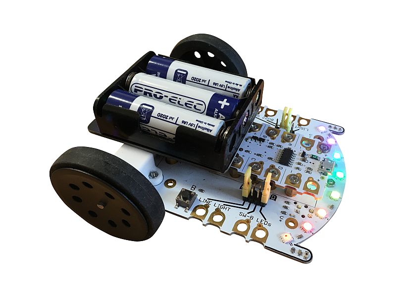
CrumbleBot 2 and CrumbleBot XL – Assembling and Coding

crumbot2_02

Purchase CrumbleBot Mk2 here


CrumbleBot Mk1

If you are looking for information on the previous versions, please check the older blog entry here


Updated Features

  • 8 Addressable RGB LEDs (‘Sparkles’)
  • Easy to use buzzer
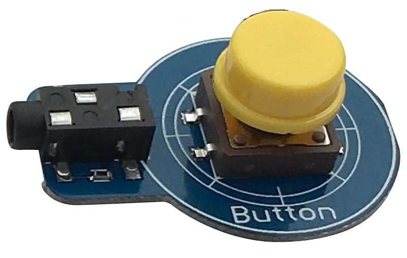
  • 2 push button switches
  • Jumpers with handles, instead of crocodile/alligator clips
  • “Wire-free”, low-profile battery holder (no USB connectors or wires to get broken)
  • Modified motor mounting positions to reduce dust ingress into the gearbox
  • Improved, smooth-running, front caster
  • Powered front accessory connector


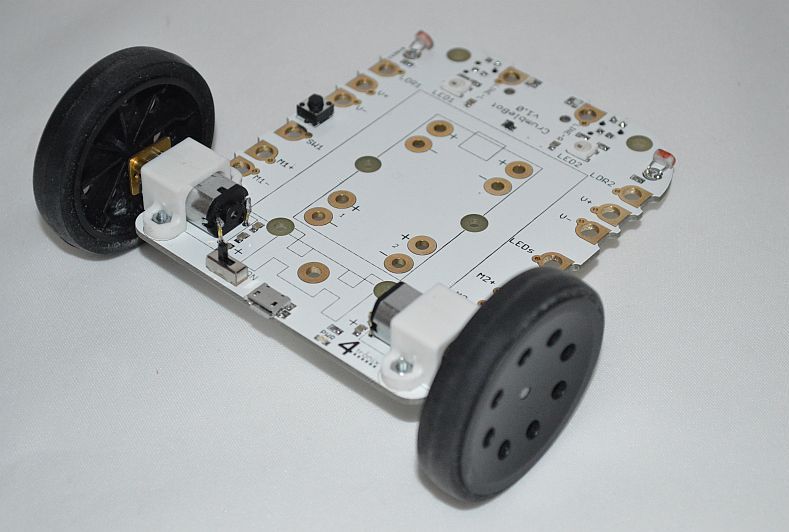
Assembling CrumbleBot Mk2 and XL

Click any photo to enlarge

Step 1 – Check you have the correct Parts

Step00

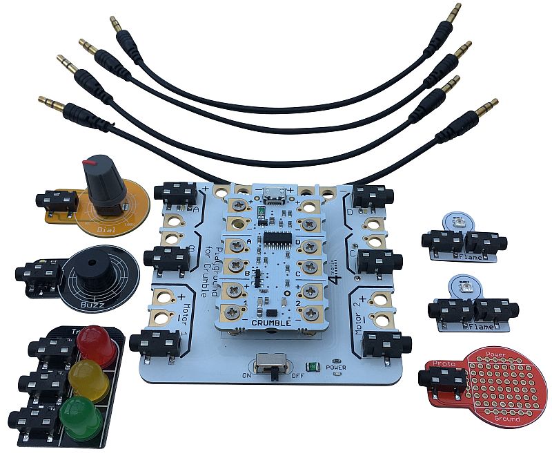
You should have the following items in the box:

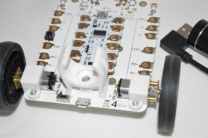
  • CrumbleBot Mk2 or XL main circuit board
  • 2 x Wheels
  • Battery Holder PCB
  • 10 x small 7mm pillars to mount Crumble (not required for version 2.1 or XL as pillars are pre-fitted)
  • 2 x larger 12mm pillars to mount battery holder
  • Caster ball and housing (Mk2 only – prefitted on XL)
  • 2 x M2, 6mm screws to attach caster (Mk2 only)
  • 2 x M2 nuts for caster (Mk2 Only)
  • 10 x 4mm M3 screws (v2.0 has 20 x 5mm) to attach Crumble
  • 4 x 8mm countersink head screws to fit battery holder
  • 4 x Yellow (colour may vary) jumpers with “handle” to select function of each connection
  • 4 x coloured 12cm jumper leads for when the little yellow jumpers can’t reach


Step 2 – Fit the Caster (Mk2 only)

Step01


Step02

Use the 2 small M2, 6mm screws to pass through the caster underneath the CrumbleBot and fit the nuts on the top of the CrumbleBot mainboard.

Caster is pre-fitted on CrumbleBot XL


Step 3 – Fit the Crumble mounting Pillars (v2.0 Only)

Step03

NB. V2.1 and XL Has these pillars ready-fitted – skip this step

V2.0: Use 10 of the small 5mm screws to fit the 10 small pillars on the top of the CrumbleBot.


Step 4 – Fit the Crumble

Step04

Use the 10 M3, 4mm (for v2.0 use the remaining 10 small 5mm) screws to attach the Crumble to the 10 pillars fitted in Step 3.


Step 5 – Fit the Battery Holder Pillars

Step05

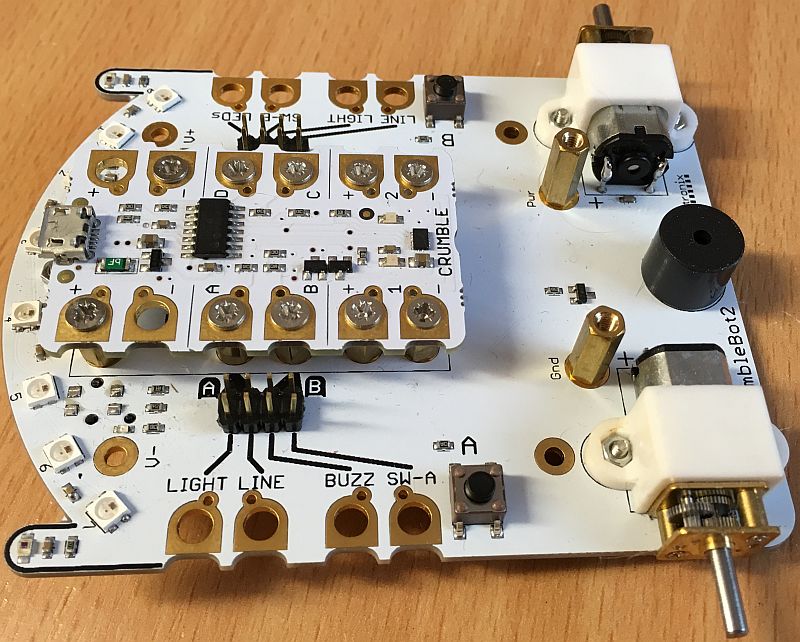
Use the 8mm screws to fit the 2 longer 11mm pillars into the holes marked “GND” and “PWR”


Step 6 – Fit the Battery Holder

Step06

User the remaining 2 longer 8mm screws to fit the battery holder to the 11mm pillars.

NB. Ensure  the switch and LED are at the rear of the robot


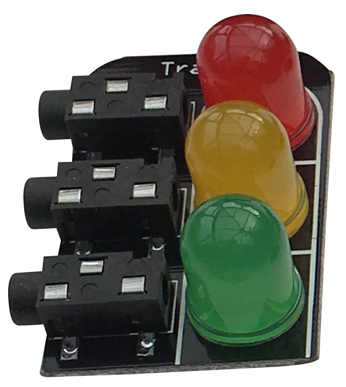
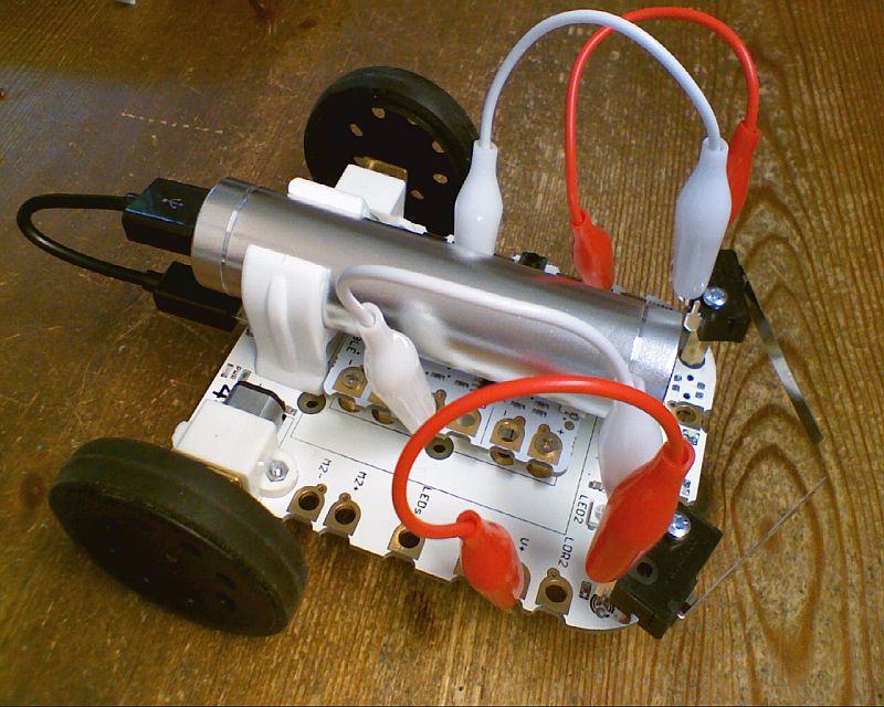
Step 7 – Add the batteries and Jumpers

Step07

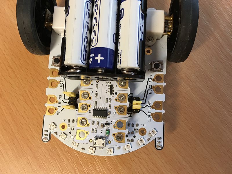
A good starting point for the jumpers is in the middle two positions on the left side, and the outer two positions on the right side.  This allows use of the line sensors, sparkles and buzzer without changing anything.

CrumbleBot XL has an extra position on the left side. This to enable the ultrasonic sensor and connect it to I/O pin A


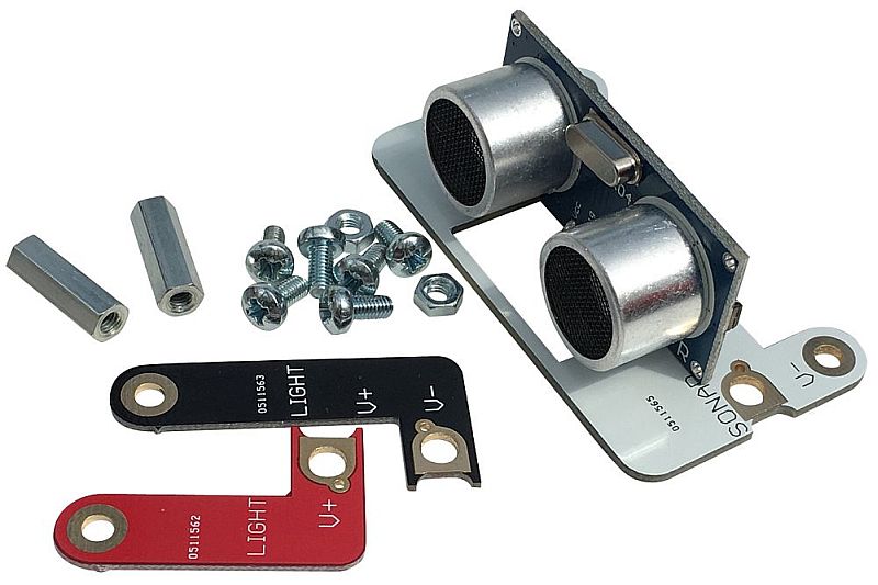
Step 8 Optional – Add the Ultrasonic Distance Sensor

IMG_1368a

Using the four 6mm screws, screw the two 20mm (11mm on XL)  pillars into the front accessory connectors. Then screw the sensor module onto the top of the the two pillars as shown above.

For Mk2, to connect the sensor to the Crumble, you must use one of the 12cm jumper wires to connect to a GPIO pin. On XL use the yello jumper in its most forward position

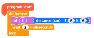
All our examples use GPIO A so wire it as shown in the photo above. (Mk2 only, remember to remove the Yellow jumper attached to GPIO A). Now you can use the distance block in the Crumble software, setting both T (Trigger) and E (Echo) to the same pin. A in this case.


Your CrumbleBot Mk2 or XL is Finished and ready for Coding!


Coding Your CrumbleBot

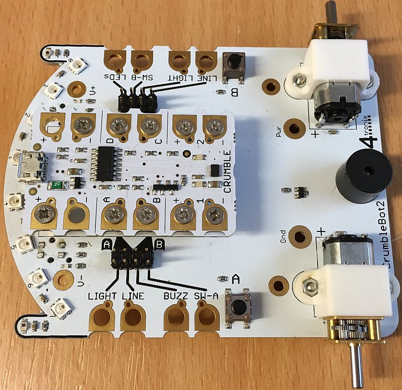
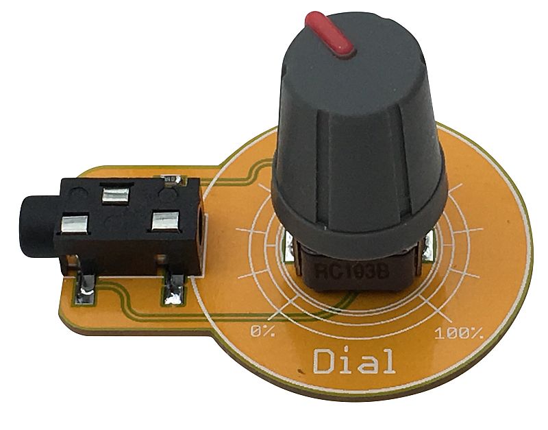
 1. Understanding the Jumpers

The Crumble has 4 general purpose IO (GPIO) connections, labelled A, B, C, D. These are all interchangeable for everything except driving Sparkles, which can only be done using GPIO D.

CrumbleBot Mk2 brings each GPIO connection to 2 positions on a jumper block and the XL adds another position for I/O pin A. The other side of each position is connected to one of the functions of the CrumbleBot. Thus, you can use the little Yellow jumpers to connect from a GPIO to one of the functions on the CrumbleBot2. For instance the top row on the left-side connector block is connected to to GPIO A (on the right of the connector block) and to the left side Light sensor (on the left of the connector block). Fitting a Yellow jumper across the top row will therefore connect the light sensor to GPIO A. If instead you connect the yellow jumper to the next row down, you would be connecting GPIO A to the line sensor. (As an aside, it is possible to connect each GPIO to 2 different signals at the same time – this won’t damage anything but will give unexpected results).

So the default settings for the yellow jumpers will connect the GPIO as follows:

  • A to the left Line sensor
  • B to the Buzzer
  • C to the right Line sensor
  • D to the 8 on-board sparkles


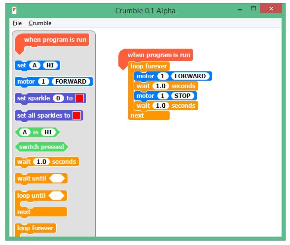
2. Driving the Motors

The Crumble has its own motor drivers which are connected directly to the motors on the CrumbleBot. You do not need to make any special connections to make these work. Each Motor is driven independently and you can select the speed (0 to 100) and direction (Forward or Reverse) in your code.

To drive the CrumbleBot2 forward, you would set each motor to the same speed Forward:

And to drive the CrumbleBot in reverse, you could set each motor to the same speed Reverse:

If both motors are going the same speed, but opposite directions, then the CrumbleBot2 will turn on the spot:

If the motors are turning different speeds, then the CrumbleBot2 will drive in an arc


3. Flashing the LEDs

The LEDs on the CrumbleBot2 are called “Sparkles” in Crumble-speak. You can easily code them to flash different colours using the colour-picker, or by setting different Red-Green-Blue (RGB) values.

First of all, make sure that GPIO D is connected via a jumper to  “LEDs” – this is the default setting of the yellow jumpers.

This bit of code continuously makes all the LEDs flash Green on and off:

Of course, you can set each Sparkle to different colours and brightnesses – they do not have to be all the same. The following code implements a “Larson Scanner” famous from the KITT car in the Knight Rider show. It’s a bit complicated, but bear with it.


4. Following a Line

The CrumbleBot2 has built-in, digital, line following sensors. Make sure that the jumpers are set to connect GPIO A to the left line sensor and GPIO C to the right line sensor. This is the default setting. The following code drives forward until one of the sensors detects a line, then it turns toward the line until the line is not detected any more. This is a very inefficient “way to do it” (algorithm). Can you find a better algorithm for following lines?

You should make the black line out of something that doesn’t reflect light, with the background being a good reflector. Black electrical tape is good and so is printing black lines on a laser printer – here is a good resource for printing line-following tracks.


5. Making a Buzz

The CrumbleBot2 contains a little buzzer (small, round and black, underneath the battery holder). This buzzes loudly (quieter if the sticker is left on the top!) when the input is set to Hi.

The default jumper settings have the buzzer connected to GPIO B, so the following code makes an annoying beep every second:


6. Acting on Switches

There are 2 switches on CrumbleBot2 SW1 (A) on the left side and SW2 (B) on the right side. You will need to move the jumpers from their default positions to use them. The following code modifies the buzzer code in 5. “Making a Buzz” so that it waits for SW1 (A) to go HI (pressed) then starts the buzzer until SW2 (B) is pressed. You will have to use a 12cm jumper wire to connect GPIO A to the SW1 (A) – not forgetting to remove the yellow jumper. So this should have:

  • 12cm Jumper wire from GPIO A to SW1 (A)
  • Yellow Jumper from GPIO B to BUZZ
  • Yellow Jumper from GPIO D to SW1 (B)


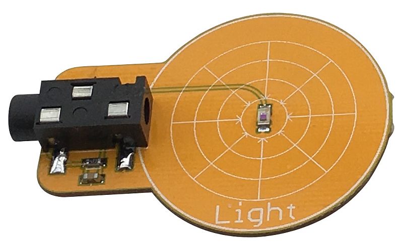
7. Following the Light

CrumbleBot2 has 2 light sensitive transistors which produce an analog value from 0 (very dark) to 255 (very bright).

We can use a similar program to the line follower. What we want to do is turn the robot to the side that has the most light. Because the light sensors can vary a lot, we must be careful that we don’t turn the robot every time there is a very slight difference in light levels, otherwise it would spend all its time turning and never move forward much. So we create a guard band in the software and make sure the light levels are sufficiently different before we decide to turn the robot. This is why we compare the X and Y variables and make sure there is a difference of at least 10, before turning.

Connect the yellow jumpers for GPIO A and GPIO C to Light


8. Use the Distance Sensor to Follow You around

Using the optional ultrasonic distance sensor, we can make the CrumbleBot2 follow us and stay the same distance away. The following code measures the distance to an object (eg. your feet). If it is too far away then the CrumbleBot2 moves Forward. If it is too close, then it moves in Reverse. This is a simple way to make a robot “friend”

Playground for Crumble, Micro:Bit & Raspberry Pi

Playground for Crumble, BBC Micro:Bit and Raspberry Pi

IMG_0999b PlayMicro03aPlayCrum_03

(Click on any image to enlarge)

 Purchase Here

Playground Overview

The Playground system allows you to connect external electronics (inputs, outputs, sensors, etc.) to your controller. Currently supports Crumble (from Redfern Electronics), Raspberry Pi and the BBC micro:bit.

The connections from the controller are converted to 3-pin 3.5mm jack connections and the connecting cables are 20cm jack cables – although longer cables can be used if required.

The separate electronic parts, Gizmos, can be used with any Playground. The exception being the Motor Gizmo, which can only be used with Crumble, as the micro:bit does not have integral motor drivers.

All of the Gizmos can be used within your programs using the built-in drivers for the relevant part.

Because each connection includes the necessary power and ground, you don’t need to wire these in separately – this transforms what can be a complicated and messy wiring setup into something tidy and more easily understood

Please check out these videos for Playground for Crumble and Playground for MicroBit


Installing Raspberry Pi Software

We have created a python library module that allows you to use the Playground for Raspberry Pi easily and quickly. You can install this from your Raspberry Pi connected to the internet as follows.

  • Download the latest version of the software using wget like this from a command line (eg. LXTerminal):
    wget http://4tronix.co.uk/pg.sh -O pg.sh
    bash pg.sh
  • This will create a new folder on your Pi in the /home/pi folder called playground (all lower case) with the playground.py library module and example files


Gizmos

IMG_0337a

Initially, we have 11 Gizmos for sale. These have been colour-coded in a similar way to our Crumbs:

  • Blue:  Digital inputs, such as a Button or Touch sensor
  • Yellow:  Analog inputs, such as a Light sensor or Dial
  • Black: Digital outputs, such as LEDs or Buzzer
  • Red:  Analog outputs such as the Servo or Motor
  • White:  Smart Pixels (aka “neopixels” or “sparkles”), individually addressable, chainable, RGB pixels (Flame, Blaze and Fire Stick)


Button Gizmo

Button_02

This provides a simple digital input to Playground. It is Active (High) when pressed and inactive (Low) when not pressed. There is a white indicator LED to show whether it is active or not.

Worksheet Links: Crumble  BBC micro:bit   Raspberry Pi


Touch Sensor Gizmo

Touch_02

This provides a digital input to PlayGround. Simply touch the pad on the sensor for it to become active (High) and release for it become inactive (Low). There is a white indicator LED to show whether it is active or not. In fact the sensor will detect your finger without actually touching, so you can do experiments to see how many sheets of paper you can cover it with before it stops working

Worksheet Links: Crumble  BBC micro:bit  Raspberry Pi


Dial Gizmo

Dial_02

The Dial Gizmo provides an analog input to your Playground. On the Crumble it will read from 0 to 256, while on the micro:bit it will go from 0 to 1023. The actual top end number will vary due to various losses in the system

Worksheet Links: Crumble  BBC micro:bit    Raspberry Pi


Light Sensor Gizmo

Light_02

The Light Sensor Gizmo is an anlog input Gizmo that reacts to the brightness of light to the sensor in the centre. It is tuned to be sensitive to daylight. The values vary from 0 (dark) to 256 (bright) on the Crumble, while on the micro:bit it will go from 0 to 1023. The actual top end number will vary due to various losses in the system

Worksheet Links: Crumble  BBC micro:bit  Raspberry Pi


Traffic Light Gizmo

Traffic_02

The Traffic Light Gizmo is a digital output Gizmo for your Playground. Each of the large 10mm LEDs will turn on when the appropriate input is set to High. There are three inputs, one for each of Red, Amber and Yellow

Worksheet Links: Crumble  BBC micro:bit  Raspberry Pi


Buzzer Gizmo

Buzzer_02

The Buzzer Gizmo is a digital output Gizmo for your Playground. When the input is set to High, the buzzer will sound and a white indicator LED will light

Worksheet Links: Crumble  BBC micro:bit  Raspberry Pi


Flame Gizmo

Flame_01

The Flame Gizmo provides a single, fully controllable, RGB pixel. This allows you to change the colour to any one of 16 million different colours. These are chainable, with both an input and an output connector. On the Crumble, these “smart pixels” are referred to as “Sparkles”, while on the micro:bit they are known as “neopixels”

Worksheet Links: Crumble  BBC micro:bit  Raspberry Pi


Blaze Gizmo

Blaze_02

The Blaze Gizmo gives you a ring of 8 , independently controllable, RGB pixels. This allows you to change the colour of any or all of them to any one of 16 million different colours. On the Crumble, these “smart pixels” are referred to as “Sparkles”, while on the micro:bit they are known as “neopixels”. These can be added onto the end of a chain of Flame Gizmos if required, or used on their own

Worksheet Links: Crumble  BBC micro:bit  Raspberry Pi


Servo Gizmo

Servo_02

As the name suggests, this Gizmo allows you to very easily connect a miniature 9g servo to your Playground. Plug it in, then program it for a 180 degree range of movement. With the Crumble, the allowable range is -90 to +90. Do not try and use it outside the allowable range.

Worksheet Links: Crumble  BBC micro:bit  Raspberry Pi


Motor Gizmo

(Not compatible with micro:bit Playground)

Motor_01

The Motor Gizmo is driven directly from the Crumble motor driver outputs – it cannot work with the micro:bit. Use the Crumble motor control blocks to set the speed and direction of up to 2 Motor Gizmos. You can build yourself a robot very easily with 2 of these

Worksheet Links: Crumble  (BBC micro:bit and Raspberry Pi not available – a prototype motor Gizmo for Pi is shown at top of page – this has a built in motor driver.)


Prototyping Gizmo

Proto_01

This simple Gizmo allows you to build your own Gizmo for those inputs or outputs that are not yet available as a ready-made Gizmo. For instance, you could make a temperature sensor, or have a controllable relay. The board has 4 holes for the Signal, 6 for each of Power and Ground, and 48 for you to use for your creation.


Ultrasonic Addons for CrumbleBot – Assembly and Use

Ultrasonic CrumbleBot Addons

IMG_0099b

IMG_0098b

Download Updated Crumble software from here

This post gives brief instructions for assembling the Static and Panning versions of the Ultrasonic addon for CrumbleBot

You will need version 25.5 or later of the Crumble Software – see the link above to download it.


Static Ultrasonic Distance Sensor

IMG_0106b

Check you have the correct parts:

  • White base PCB with ultrasonic sensor
  • Red Positive power connection PCB
  • Black Negative power connection PCB
  • 2 x 15mm Pillars
  • 6 x 6mm Screws
  • 2 x Nuts

Fit the Distance Sensor to the CrumbleBot

  1. The Black negative power connector PCB is fitted on the left side of the CrumbleBot with the writing facing upwards.
  2. Use a screw and nut to screw the connector PCB into the hole marked V-. Do not tighten the screw
  3. Screw in the Red positive power connector PCB onto the right side of the CrumbleBot using a screw and nut into the connector marked V+. Don’t tighten the screw.
  4. The other ends of the two power connectors PCBs should line up with the 2 mounting holes at the front of the CrumbleBot
  5. Now use 2 more screws to fit the 15mm pillars onto the top side of the CrumbleBot, feeding the screws through the mounting holes, through the power connector PCBs and into the pillars
  6. Finally, use the 2 remaining screws to fit the main ultrasonic sensor board to the tops of the 2 pillars
  7. Now tighten all the screws so everything is fixed tightly
  8. It should now look like the photo below

IMG_0098b

Using the Static Distance Sensor

  • Ensure you have downloaded the latest version of the Crumble Software (must be at least v25.2)
  • Use a crocodile clip cable to connect one of the inputs (A, B, C or D) to the connection marked “SONIC” on the sensor board
  • Use the “Distance” block and set both ‘T’ and ‘E’ to the same pin as you are using to connect the sensor (The example below shows it connected to input A)
  • The example code below simply gets the distance and saves it into variable t. You can look at the variables and see the distance change as you move your hand in front of the sensor

sonic01


Panning Ultrasonic Distance Sensor

IMG_0103b

Check you have the correct parts:

  • White base PCB with ultrasonic sensor and 4-pin connector
  • Larger White PCB with servo and 4-pin connector
  • Red Positive power connection PCB
  • Black Negative power connection PCB
  • 2 x 25mm Pillars
  • 6 x 6mm Screws
  • 2 x Nuts
  • 4-way Female-Female 10cm Cable (various colours)


Fit the Distance Sensor to the CrumbleBot

  1. The Black negative power connector PCB is fitted on the left side of the CrumbleBot with the writing facing upwards.
  2. Use a screw and nut to screw the connector PCB into the hole marked V-. Do not tighten the screw
  3. Screw in the Red positive power connector PCB onto the right side of the CrumbleBot using a screw and nut into the connector marked V+. Don’t tighten the screw.
  4. The other ends of the two power connectors PCBs should line up with the 2 mounting holes at the front of the CrumbleBot
  5. Now use 2 more screws to fit the 25mm pillars onto the top side of the CrumbleBot, feeding the screws through the mounting holes, through the power connector PCBs and into the pillars
  6. Then use the 2 remaining screws to fit the servo board to the tops of the 2 pillars
  7. Now tighten all the screws so everything is fixed tightly
  8. Push the Board containing the ultrasonic sensor onto the top of the servo and use the screw inside the servo parts bag to fit it more permanently (actually, you can leave this off until you are sure you have it set to the centre position when the servo is centred)
  9. Finally, use the 4-way cable to connect the Sensor PCB to the Servo PCB. Make sure that the wires do not cross over. So for example, if you have Brown, Red, Yellow Orange at the top, then you must also have Brown, Red, Yellow, Orange at the bottom. (your wires may be completely different colours, so just ensure they are in the same order at the top as at the bottom)
  10. You should now have something like the photo shown below

IMG_0099b


Using the Panning Distance Sensor

  • Ensure you have downloaded the latest version of the Crumble Software (must be at least v25.2)
  • Use a crocodile clip cable to connect one of the inputs (A, B, C or D) to the connection marked SONIC on the servo board
  • Use another crocodile clip cable to connect one of the inputs to the connection marked SERVO on the servo board
  • Use the “Distance” block and set both ‘T’ and ‘E’ to the same pin as you are using to connect the sensor (The example below shows it connected to input A)
  • Use the “Servo” block to set the position of the servo from -90 degrees to +90 degrees. 0 degrees should be straight ahead
  • The example code below sets the servo to straight ahead, then gets the distance and saves it into variable t
  • If the servo is not pointing straight ahead, pull off the top PCB with the sensor on and fit it onto the servo again so it is pointing ahead. Then tighten the screw.

sonic02


CrumbleBot – Assembling, Coding, Extending

CrumbleBot Assembly and Usage

crbot_Light01a

Download a PDF of this Article

Introduction

The CrumbleBot is a fantastic way to introduce coding with the Crumble to children of all ages, and especially primary school children. It provides a ready-built platform to experiment safely and easily with analog and digital, inputs and outputs. It moves, it shines lights and it reacts to its environment – but only if your coding tells it to.

In this guide we take you through the process of assembling the CrumbleBot and show you how to start coding to do real-world physical computing. Before you know it, the children will be telling you how to improve it!

See the end of this article for some program examples:

  1. Know your CrumbleBot
  2. Let’s Get Moving
  3. Let There be Light
  4. Follow that Line!
  5. Finding the Light
  6. Check that Switch!
  7. Obstacle Avoiding


Assembling CrumbleBot

Nothing could be simpler really, but let’s break it down into a few easy steps

First check out this video from Inspired Minds


Step 1 – Check you have all the Parts

cbb02

You should have the following items in the CrumbleBot kit and you will also require a Crumble (of course!)

  • Main CrumbleBot Circuit board (white, 100 x 80mm) with all components fitted, including 2 micro metal gear motors
  • 2 black wheels
  • Ready-assembled front caster with 2 screws
  • 6 mounting pillars to fit the Crumble: 5mm, M2.5, Female-Female
  • 12 small screws to fit the pillars: 4mm, M2.5, countersunk head


Step 2 – Fit the Wheels to the Motors

cbb04

The wheels simply push onto the axle. Stop pushing when the axle is flush with the outside of the wheel


Step 3 – Fit the Front Caster

cbb05

Use the 2 self-tapping screws in the bag with the caster to screw into the pre-assembled caster assembly. DO NOT overtighten


Step4 – Fit the Mounting Pillars for the Crumble

cbb06

There are 6 pillars. The four at the back must be placed as shown as these connect the motor outputs from the Crumble to the motors on the CrumbleBot.

The front 2 pillars must be placed one next to a positive (+)  and one next to a negative (-) connector. It doesn’t matter if you use both on the left side, both on the right, or one left and one right. Juste ensure you have one +ve and one -ve.

Screw the pillars in as tight as you can so they won’t move when the Crumble is attached.


Step 5 – Fit the Crumble

cbb07

Use the remaining 6 small screws to fit the Crumble to the pillars.

Ensure that the USB connector on the Crumble faces the front of the CrumbleBot as shown in the photo above.

You have now built the CrumbleBot. That was easy wasn’t it!


Now to fit the battery pack – there are three options:

  • If you have the USB rechargeable battery pack, go to Step 10
  • If you have the standard 3xAA battery holder with wire leads, then go to Step 6B
  • If you have the new “Wire-Free” 3xAA holder, then continue here with step 6A

Step6A – Fitting the new “Wire-Free” 3xAA Holder

BattHolder_01

The new battery holder is fitted to its own black PCB with switch, indicator LED and fuse.

This complete assembly screws to the top of the 20mm pillars supplied.

BattHolder_04

Power is taken from the bottom of the pillars using the supplied “Battery Adaptor” PCB that is fitted underneath the main PCBA

Step 7A- Fit the 20mm Mounting Pillars and Battery Adaptor

BattHolder_03

Use the 2 longer 6mm CSK screws included with the battery adaptor to fit the front of the battery adaptor into the small pillars holding the Crumble

Use the long 8mm screws to fit the rear of the battery adaptor to the 20mm pillars

Now go to Step 8


Step 6B – Fitting the standard 3xAA Battery Holder with Wires

cbb08

Check you have the following:

  • 3xAA battery holder with micro-USB connection
  • 2 long pillars: 20mm, M2.5, Female-Female
  • 4 long scres: 8mm, M2.5, countersink head


Step 7B – Fit the Battery Mounting Pillars

cbb09

The two pillars fit directly behind the Crumble as shown in the photo above.

Screw the pillars as tightly as possible so they won’t move when the battery holder is attached


Step 8 – Attach the 3xAA Battery Holder

cbb10

Use the 2 remaining 8mm screws to screw the battery holder to the mounting pillars.

Fit it with the cable to the front of the CrumbleBot, then the extra length of cable can pass over the battery holder instead of trailing on the ground


Step 9 – Plug in the USB Connector

cbb11

You have now completed your CrumbleBot with AA battery pack. Time to learn how to code!


Step 10 – Attaching the USB Battery Holder

cbb13

Check you have the following:

  • White plastic clip for holding the battery
  • USB battery stick (various colours may be supplied). These are 2600mAH batteries
  • Fixing screw: 12mm, M3, countersink head
  • Fixing nut: M3
  • USB to micro-USB cable (various colours/styles may be supplied)


Step 11 – Attach the Mounting Clip

cbb14

Pass the screw through the plastic pillar, through the CrumbleBot PCB and into the nut. Tighten well

Twist the clip if necessary to make it point forwards

cbb15


Step 12 – Fit the USB Battery Pack

cbb16

Push the USB Battery Pack through the clip from the front. Do not attempt to clip it in from above as it is very stiff.

Use the USB cable to connect the Battery Pack to the USB connector on the CrumbleBot

cbb17

You have now completed your CrumbleBot with USB Battery Pack! That was easy wasn’t it? Let’s go and code it


Step 13 – De-Slipping the Crocodile Clips

The crocodile clips can be very slippy within the soft rubberised covers which can make them difficult to grip and clip onto things. We therefor provide some rubberised tubular sleeves.

  • Cut each sleeve in half, so you have 4 pieces
  • For each end of the 2 crocodile leads:
    • Slide off the rubberised cover
    • Push on a half-sleeve onto the exposed metal tab
    • Slide the rubberised cover back on
    • If you clip the crocodile clip to something first, then it is easier to remove and replace the rubber cover


 Coding for your CrumbleBot

** Please note that only the motors are permanently connected. All other features require one or more croc clips (included) to be connected from the Crumble to the Crumblebot. This allows more features to be included than can be active at any one time.

1 – Know your CrumbleBot

KnowCrumbleBot01a

The CrumbleBot looks simple, but it has an amazing array of features just waiting to be used by you and your Crumble:

  • Micro-USB connector. This is the power input to the CrumbleBot and powers everything on the CrumbleBot including the Crumble. It cannot be used to program the Crumble
  • On-Off Switch. This, er, switches the power on or off. When the power is on then the Blue indicator LED near the switch is lit
  • 2 micro metal gear motors that can be driven independently at varying speeds in either direction, making it easy to go forwards, backwards, spin on the spot or do sweeping turns – all at your command. The motors are permanently connected to the Crumble via the small mounting pillars. You do not need to use croc clips to operate them
  • 2 line sensors with indicator LEDs. These are placed at the front of the CrumbleBot and detect whether a black line or a reflecting surface is underneath. You can use black insulation tape as your line and stick it directly to the floor or desk. Or you can print out a thick black line on paper (make sure the line is about 1cm wide). If a line sensor detects a line, then the corresponding indicator LED (Red for left, Green for Right) will come on. These provide DIGITAL INPUTS to the Crumble. HI for detecting a line; LO for a reflecting surface
  • 2 light sensors. These are ANALOG INPUTS to the Crumble and will give a varying value between 0 (totally dark) and 255 (very bright) depending how bright the light shining on them is. Use these to search out the brightest place to be, or the darkest place to hide!
  • 2 Sparkles. When connected directly to the Crumble these are Sparkle 0 (labelled LED1) and Sparkle 1 (labelled LED2). You can control the brightness and colour of these Sparkles independently – why not use them to show what your CrumbleBot is doing?
  • Small tactile switch. This is a DIGITAL INPUT to the Crumble. When pressed it is HI, otherwise it is LO


2 – Let’s Get Moving

code01

The program above is all you need to make your Crumble move Forward. Motor1 is the Left Motor; Motor 2 is the Right Motor. If they both move forward, then the CrumbleBot with move forward in a straight line*

* “Straight Line”. All motors are very slightly different from each other. This means that even if you set the same speed for each motor, they will not move at exactly the same speed and the CrumbleBot will turn to one side or the other. You can correct for this when it is important (it isn’t always important at all) by setting a slightly different speed for each motor. For instance, we found that the CrumbleBot is moving slightly to the left, so we speed up the left motor to 80% like this:

code02


You can set the speed of each motor independently to between 0 and 100%. You will find that the motors won’t have enough power to turn if the speed is set too low; maybe less than 20% will be too low for the motors to move.

Setting the speed to 100% will move the motors at their fastest speed.

Note: You can actually set the speed of the motors to negative values. So setting it to go Forward -75%, is exactly the same as setting it to Reverse 75%


If you want the CrumbleBot to spin left, then set the left motor to Reverse and the right motor to Forward, as shown below:

code04


If you want the CrumbleBot to spin right, then do the opposite: set the left motor to Forward and the right motor to Reverse:

code03


3 – Let There be Light!

Let’s get the Sparkles on the Crumble Bot going.

First we need to connect the D output of the Crumble to the LEDs input on the CrumbleBot

Sparkles_Wiringa

Then the Left is Sparkle 0  and the Right is Sparkle 1

The we can use the Sparkles commands in the Crumble software to flash them. The program below flashes them Blue alternately, Left then Right then Left then…


4 – Follow That Line!

The CrumbleBot has 2 line follower sensors on the underneath at the front. These have associated LEDs which light up when a black (non-reflective) line is detected. Red for Left (Port) and Green for Right (Starboard). These LEDs are active any time the CrumbleBot is powered up; they do not require any software on the Crumble.

To use the line follower sensors, you must connect them to the inputs you want to use. In this demo, we will use inputs B and C. See the photo below for the connections:

crbot_Line01a

A basic program for this is shown below. If the left sensor detects a line (if B is Hi) then the robot should turn Left. If the right sensor detects a line (if C is Hi) then the robot should turn right. Otherwise it should go forward

You can easily extend this program so that it stops, or turns round if both sensors detect a line, or you can make rules for what will happen at a junction


5 – Finding the Light

The CrumbleBot has 2 light dependent resistors (LDRs) at the front left and the front right. These produce analog values from 0 to 1023. 0 means there is no light at all, whereas 1023 means there is lots of light. In practice you will only see readings well within these 2 extremes.

Let’s use the inputs B and C again, but this time we will read the analog values. Wire up the CrumbleBot as shown below:

crbot_Light01a

We can use a similar program to the line follower. What we want to do is turn the robot to the side that has the most light. Because the light sensors can vary a lot, we must be careful that we don’t turn the robot every time there is a very slight difference in light levels, otherwise it would spend all its time turning and never move forward much. So we create a guard band in the software and make sure the light levels are sufficiently different before we decide to turn the robot. This is why we compare the X and Y variables and make sure there is a difference of at least 10, before turning

You will note that there is a delay of 100 milliseconds at the end of each loop. You can experiment with different speeds, guard bands and delays to see which is fastest to get the robot to a specific spot near the light

Why not try and change the code so the robot finds the darkest place to hide?


6 – Check that Switch!

The CrumbleBot has a little switch on it that you can use to change what is happening in the program or simple to react by switching on LEDs.

Let’s start by connecting the switch to input B

Switch_Wiringa

Now we can write a program that checks to see if the switch is pressed. It will be Hi if pressed, or Lo if not pressed.

This simple program turns the left motor on when the switch is pressed and stops it when the switch is released


7 – Adding Extra Sensors – Obstacle Avoider

The CrumbleBot has 2 holes near the front that you can use to add sensors. In this section we are using the microswitch kit to add obstacle sensors to the CrumbleBot.

Because these sensors are not part of CrumbleBot itself you will have to connect power as well as the signal to each microswitch. So you will need 4 short croc clips altogether, 2 on each side as shown:

Avoider02

Avoider03

Connect the Power to the middle pin of the microswitch, and connect the B or C inputs to the  “Normally Open” or NO contact. When the microswitch hits an obstacle then the corresponding input will be a Hi

For the Avoider program, which is similar to the line follower and light seeker, we make the robot reverse and turn when it hits an object. If the left microswitch hits, then we turn right, and if the right microswitch hits then we turn left. This gives us a chance of avoiding the object. The program also recognises when both switches hit an object together and stop the robot.


Understanding the Number Crumb

How the Number Crumb Works

Number02

The Number Crumb is designed to provide a simple display output for your Crumble. At this time, there is no native display for the Crumble and you have to give indications via the 4 outputs on the Crumble – perhaps lighting LEDs or sounding a buzzer.

The Number Crumb, however, is very different. There is a microprocessor on the Crumb which interprets the speed (PWM) information that you send to the motor on the Crumble.


Purchase Number Crumb here


Connecting the Number Crumb

Number06

  • Connect power to the Number Crumb. The photo above shows Red for +ve and Black for -ve
  • Then connect the motor outputs (either Motor 1 or Motor 2, it doesn’t matter which). Ensure that you connect the positive terminals together and the negative terminals together
  • It doesn’t harm anything if you swap them over, but the Number Crumb with show negative numbers instead of positive, and vice versa


Programming the Number Crumb

To set a value on the Number Crumb, simply set the number you want into the “Motor Forward at nn %” block. Change nn to the number you want.

For example, the program above uses the variable x and starts at -30, then counts up to +100

The program below takes the input from an analog input (such as the Slider Crumb, Dial Crumb, or Light Sensor Crumb) and displays a value on the Number Crumb


Number Crumb Firmware

The Number Crumb has an ATMega328P on the PCB (under the display) which is configured as an Arduino Uno complete with bootloader. So you can reprogram the firmware to do whatever you want to do.

It has 2 digital I/O pins (D2 and D13) and then 10 pins are connected to the display via resistors.

There are 3 versions of the Number Crumb firmware in the field:

  1. Was released only for prototype Number Crumbs. This goes straight into number display mode when powered up
  2. Later prototypes and the first few production Number Crumbs had version 2. This displays “02” for a couple of seconds when powered up
  3. Currently shipping is version 3. This displays ” 3″ for a couple of seconds when powered up.

The changes between the versions are mostly to do with stability of number display

  1. The input signals from the Crumble, together with the resolution of the onboard counter leads to variations in the number displayed which was not always the same as the number input into the Crumble’s motor
  2. Version 2 made big changes to this accuracy, but still had some numbers that were difficult to display reliably. In addition, it was quite slow reacting to new numbers which meant that it was not able to keep up with the counting program above. There was also a lot of flicker for numbers -100, 0 and +100
  3. The algorithm for counting has been improved so the resolution is better and the averaging and display algorithms have been more tightly integrated so that the flashing/flickering disappears. Leading zeros have been suppressed, which allows a minus sign to be used for numbers -1 to -9 instead of the dots.


The software essentially times the edges of the motor drive signal. PWM (Pulse Width Modulation) sends a pulse at a fixed frequency and varies the width of the pulse to increase or decrease the speed of the motor. The Number Crumb accurately times the edges and can work out from that what number was set in the motor control block of the software. Version 1 or the firmware would work with most PWM drivers, but version 2 and 3 are increasingly tuned to work very closely with the Crumble PWM and would probably give inconsistent or nonsensical values with other PWM drivers.


Programming the Number Crumb

There are six header holes on the Number Crumb that allow you to directly plug in a suitable CP2102 and reprogram the Crumb using the Arduino IDE. Set your board type to Uno and ensure you select the CP2102 as your port/device.

If you have firmware version before 3 and want to upgrade it, you can either do it yourself (contact us for the program) or send it back to us and we will reprogram it for you.


Crumbs for Crumble Controller

Crumbs – Addon Components for your Crumble Controller

AllCrumbs01a

Purchase the Crumbs Here

Also check out our Crumble Starter Guide

Download a PDF of this guide complete with Code examples from here.

 Style of Crumb

  • Analog input: These Crumbs are coloured Yellow and provide a continuously varying input for the Crumble which can be read and used with the A. B, C and D connections
    • Slider
    • Dial
    • Light Sensor
    • Motion Sensor
  • Digital input: Blue. These Crumbs provide a simple On/Off input to the Crumble controller. Again would be used with the A, B, C and D connections
    • Button
    • Magnetic Hall Effect Switch (previously Reed Switch)
    • Proximity Sensor
    • Dual Capacitive Touch Sensor
    • PIR sensor
    • Ultrasonic distance sensor
  • Analog output: Red. These Crumbs allow the Crumble to continuously vary the device: speed of the motor, brightness of the Sparkles, Number shown on the display, position of the servo
    • Motor
    • Number Display
    • Servo
  • Digital output: Black. These Crumbs can be set either On or Off by the Crumble
    • Traffic Lights
    • Buzzer

Using Crumbs

Most Crumbs require a 5V Power and Ground connection to be made before they work fully. Sometimes this is to power the on-board electronics and sometimes, simply to ensure that the indicator LED works as expected.

The Crumbs are designed so that the Power and Ground (5V and 0V) can be applied to either the left or the right side. It doesn’t matter which you use. You can then use the opposite side to take the power to any other Crumb that you are using, as shown in the picture below:

ServoSlider03

We recommend using short crocodile clips to join the Crumbs together as it reduces the amount of wiring considerably and the whole experiment becomes clearer to understand

Although the Crumbs are generally protected against connecting power on the wrong way round, or onto the wrong pin, it is recommended that you use some sort of colour coding so that the children can see how the positive power flows (using Red wires) or the negative with Black wires. You can use Green as an alternative to Black if you run out, but Yellow, White and Green are good colours to use for the general purpose inputs/outputs or motor outputs.

Where there are 2 crocodile lead connection pads next to each other on a Crumb (or indeed the Crumble) the two small holes that form part of the pads are designed to be exactly 5mm apart so that a standard 2-pin 5mm screw terminal can be soldered on. This allows you to use standard wires of exactly the correct length that are simply screwed into the terminal blocks as shown below:

termBlock02

Analog Input Crumbs (Yellow)

SLIDER

Slider05a

This requires Power and Ground to be connected and the output connected to A, B, C or D. The analog value read will be in the range 0 to 255, though in practice the power is not at 5V so the top end number will be lower

Sliding the slider to the left will give a value of 0, to the right will give the maximum number (probably 200 to 255)

The program below reads the value from the Slider Crumb connected to Input A, into the variable X. You can see the value being displayed on the left: x = 226

DIAL

Dial03a

This requires Power and Ground to be connected and the output connected to A, B, C or D. The analog value read will be in the range 0 to 255, though in practice the power is not at 5V so the top end number will be lower

Turning the Dial anti-clockwise will give a value of 0, turning it clockwise will give the maximum number (probably 200 to 255)

The program below uses the value read from the Dial Crumb connected to Input A to set the speed of Motor 1. Note that the maximum value for motor speed is 100, so we divide the value from the Dial Crumb by 3 to be sure it fits into this range.

LUX/LIGHT

lux01

This requires Power and Ground to be connected and the output connected to A, B, C or D. The analog value read will be in the range 0 to 255, with 0 being total darkness and 255 being extremely bright.

Covering the light sensor completely will reduce to the minimum value and shining a bright light on it will achieve the maximum

The program below uses the value from the Light Sensor Crumb to set the brightness of the Red element of Sparkle 0. So in a dark room, the Sparkle won’t be as bright as in a bright room.

MOTION

Motion01a

This requires Power and Ground to be connected and the outputs connected to A, B, C or D. The analog values read will be in the range 0 to approximately 125

You can tilt the board in X, Y or Z axis and the appropriate output will change its value. Maybe you can use this to steer a robot?

The program below extends the program for the Light Sensor Crumb by using all three axes of the Motion Sensor to set the three colour elements (Red, Green and Blue) of the Sparkle. So twisting and turning the Motion Crumb will change the brightness and colour of the Sparkle.

Digital Input Crumbs (Blue)

BUTTON

Button02

This requires the Power to be connected in order for the button to operate. In addition, you should connect the Ground so that the indicator LED operates.

When the button is not pressed, the output is 0 (Low) and the indicator is Off

When the button is pressed, the output is 1 (High) and the indicator is On

The program below starts Motor 1 running when the button is pressed and stops it when the button is released:

ULTRASONIC DISTANCE SENSOR

This requires the Power and Ground to be connected in order for the sensor to operate. You can connect the centre output to any of the 4 Crumble inputs (A, B, C or D).

Both the Trigger (T) and the Echo (E) are connected to the same pin, so use the same pin letter in both for the distance block.

Also, it is important that there is sufficient delay between repeated readings for the sensor to recover

The program below repeatedly reads a value and you can see it on the Crumble app by watching variable t:

MAGNETIC HALL EFFECT SWITCH

Hall02a

This requires the Power to be connected in order for the Hall Effect switch to operate. In addition, you should connect the Ground so that the indicator LED operates.

When a magnet is not present, the output is Low)and the indicator is Off

When a magnet (eg. a fridge magnet) is brought towards the sensor, the output is High and the indicator is On

The program below counts the number of pulses received from the Magnetic Switch Crumb. Maybe the magnet is on a wheel spinning round past the Crumb and this is counting the revolutions of the wheel?

PROXIMITY SWITCH

Prox05

This requires the Power and Ground to be connected in order to operate.

When there is no object near the sensor, the output is 0 (Low) and the indicator is Off

When an object (eg. a hand) is brought above the sensor, the output is 1 (High) and the indicator is On

The sensitivity is set such that a finger or hand would trigger it within about 2 to 3 cm. A reflective white card would be about 10cm

The following program waits for the trigger from the Proximity Crumb connected to input A then switches on the Buzzer connected to output B for 1 second

CAPACITIVE TOUCH SWITCH

Touch06

This requires the Power and Ground to be connected in order to operate.

When nothing is touching the sensor pads, the outputs are 0 (Low) and the indicator is Off

When a finger touches the sensor, the output is 1 (High) and the indicator is On

You can attach other objects such as pieces of fruit to the external inputs – give the system a minute or so to settle down (or remove and replace the power to reset it) after you change the connections

The program below uses the 2 outputs from the Touch Sensor Crumb connected to Inputs A and B to control 2 motors and steer a robot left or right

PIR (PASSIVE INFRARED) SENSOR

PIR03

This requires the Power and Ground to be connected in order to operate.

When nothing moving is detected, the outputs are 0 (Low) and the indicator is Off

When movement is detected , the output is 1 (High) and the indicator is On

The program below flashes lights (on Output B) and Sounds a Buzzer (on Output C) when movement is detected

Digital Output Crumbs (Black)

TRAFFIC LIGHTS

traffic01a

This requires the Ground to be connected and the Red, Amber and Green connections made to your choice of A, B, C or D on the Crumble

Setting the appropriate output on the Crumble to Hi will light the LED on the Crumb as well as the related LED on the Pi-Stop if one is plugged in

The following program runs a basic traffic light sequence with Red connected to A, Amber to B and Green to C

BUZZER

Buzzer03a

This requires the Ground and Power to be connected as well as the input connection made to A, B, C or D on the Crumble

Setting the output on the Crumble to Hi, will sound the Buzzer and light the indicator LED. Note that if the power isn’t connected, the indicator LED will still light, but the buzzer won’t sound.

The follow program plays a sort of Morse code SOS on the Buzzer Crumb connected to output A. (in fact it just does the first ‘S’ otherwise it would be a bit long)

Analog Output Crumbs (Red)

MOTOR

motorv2_04a

This requires the two terminals on the Crumb to be connected to the Motor1 or Motor2 outputs on the Crumble

There are 3 sets of the motor connector pairs. They are all identical, but make it easier to connect from different sides if for instance you use them to make a robot or similar

Setting the Motor Speed to 100 will turn the motor approximately 2 turns per second (120 rpm). The motor will stop turning if the speed setting is below about 20

If you connect + to + and – to – from Crumble to Motor Crumb, then FORWARDS = anticlockwise and REVERSE = clockwise.

The following program controls 2 motors to move a vehicle Forwards, Backwards, Spin Left, Spin Right and Stop continuously.

NUMBER

Number02

This requires Power and Ground to be connected as well as M+ and M- to be connected to the Motor1 or Motor2 outputs on the Crumble

Setting the motor speed to any number will cause that number to be shown on the display

Forwards is shown directly (eg “75”) but Reverse adds the decimal points so will show “7.5.”

See this blog entry for more information on using this Crumb

The program below simply counts up from -30 to +100 continuously:

SERVO

servo (5)a

This requires Power and Ground to be connected as well as the centre connection to one of the outputs on the Crumble

Use the Servo command in the Crumble software to set the position of the servo

** Ensure that you do not try and set the servo outside the range of -90 to +90 or unpredicatble movements may occur

The following program uses the Slider or Dial Crumb connected to input A to adjust the position of the servo on Output B:

Crumble Controller – Coding & Electronics for Primary Classrooms

Crumble – Easy Peasy, Lemon Squeezy

Related Posts:

Guide to Crumbs

Assembling CrumbleBot


crumble03a

The Crumble controller is a tiny circuit board, only 33 x 52mm that allows young children (and their teachers) to quickly and very easily learn coding and some simple electronics.

Physically, the Crumble is connected to other components using crocodile leads (“croc clips”), whilst in the software (which runs on a PC and Mac – Linux is coming soon) everything is done visually using drag and drop or simple clicks for selections.

Crumble04

Simple drag the elements you want onto the stage, click on the selections (eg On and Off, Motor1 or Motor2) and press Go. The program is sent directly via USB to the Crumble and starts to run immediately. Even better, the Crumble never forgets its program, so you can power it back up next day or even next year and it will start running the last program downloaded to it.

The hardware is designed very cleverly so the 4 connections labelled A, B, C and D can be either Inputs or Outputs and they will automatically change based on what you use them for in the program. No need to worry younger children with setting things up first, Crumble just works out what they want to do and does it directly.


What Do I need to Get Started?

Ideally, purchase one of our starter kits and include a battery holder. What you need is:

  • The Crumble controller itself
  • Micro-USB cable
  • Optionally – Something to use as an output (eg an LED or two, a motor, Sparkle, etc.)
  • Optionally – Something to use as an input (eg. a switch or a light sensor)
  • If you want to drive Sparkles or motors, then you will need a battery holder which you can connect to the Crumble using croc clips
  • Download the software (PC or Mac available now, Linux coming soon) from here
  • We are developing a number of “Crumbs” to use with the Crumble. Currently available or under development are:
    • Sparkles – full RGB LEDs
    • Slider – Analog input slide controller
    • Dial – Analog input rotary control
    • Lux – Analog input light sensor
    • Motion – Analog input 3-axis motion sensor
    • Button – Digital input press button
    • Reed – Digital input magnetic reed switch
    • Proximity – Digital input proximity detector
    • Touch – Digital input touch pads
    • Motor – Analog output DC motor
    • Number – Analog output Numerical display
    • Servo – Analog output positional servo
    • Traffic – Digital output LEDs in Red, Amber, Green with PiStop support
    • Buzzer – Digital output Buzzer with indicator LED

Visit THIS LINK to learn more about our Crumbs

Hello World – Flashing an LED

You can connect the Crumble outputs (A, B, C and D) directly to LEDs to turn them on and off. Remember the LEDs only work in one direction, so make sure you connect the long lead (positive) to the output terminal and the shorter lead (negative) to the ground terminal (-). You won’t damage anything by putting it the wrong way round, it just won’t operate.

led01

In the photo above, a blue LED is connected from A to the long lead (using the Yellow croc clip) and from the short lead to Ground – terminal (using the Green croc clip)

The program to flash it forever looks like this

Setting output A to HI, switches on the LED. Setting to LO switches the LED off. How simple is that?

Now extend this by connecting different colour LEDs to the different outputs (B, C and D) and see if you can make a traffic light sequence!


Doing something with an Input

There are 2 types of input devices that you can use:

  1. Digital inputs (such as a switch) that can be On or Off
  2. Analog inputs (such as a light sensor) that can be any value from 0 to 255. (these numbers are arbitrary and chosen by the Crumble designers to match the internal hardware. The numbers do not mean anything in the “real world”, except that 0 is the smallest value and 255 is the largest value)

In the 4tronix standard starter kit we include an LDR (Light Dependent Resistor) which is an analog input device. For this to operate, one end (it doesn’t matter which end) is connected to a positive output and the other end goes to the input. For the positive output you can use one of the (A, B, C, D) terminals – or the 5V (+) terminal if you have power connected from a battery pack. Note that the + terminal is not powered from the USB input, only from a separate battery pack.

ldr01

Here red and white croc clips are connected between C, D and the two leads on the LDR. The yellow and green croc clips are still connected to the blue LED from the example above.

The following program uses the analog values (between 0 and 255 remember) to set the delays in the flashing loop. The smaller the number, the faster the LED flashes. The number is smallest when the LDR is darkest – higher numbers for brighter lights.

The first command is to set output D to HI. This provides the positive signal for the LDR.

Note that we have used the “wait … milliseconds” block instead of “wait … seconds”. Waiting 255 seconds between flashes might be too long!

The time to wait between flashing HI and flashing LO is simply the analog value of the LDR. The brighter the light, the bigger the analog value and the longer the flashes.


Driving the Sparkles

Sparkles are individual RGB (Red, Green, Blue) LEDs that can be connecting in a long chain (up to 32 with the current software) and each can be set to a different value. These are also known as “neopixels”. Sparkles require a 5V power connection which can be from the + terminal on the Crumble (if a battery pack is connected) or from one of the A, B, C outputs set to HI. If using one of the A, B, C outputs then you can only use 1 or 2 Sparkles as they cannot provide enough power for more.

Sparkle05

In the photo above, we have used output C to connect to the Sparkle’s power + input. The data input of the first Sparkle in the chain must be connected to the D output on the Crumble. This first Sparkle is called Sparkle 0, the next is Sparkle 1 and so on. Each Sparkle must be connected to power and Ground: use the + and -terminals from the previous Sparkle for this. Each Sparkle also needs an input signal. The input for the first Sparkle is the Crumble D output, but after that use the output from one Sparkle and connect it to the input of the next in the chain

Sparkle03

You can flash the Sparkles using a simple loop as shown above. Notice the first statement sets C to HI to provide power for the Sparkle. We only have one Sparkle in our chain, so this is Sparkle 0. You can select any colour you like for each Sparkle just by clicking on the coloured square.


Driving Motors

In our Super and Ultimate Crumble kits, we also include DC motors. Again, these can be driven directly by the Crumble, but you must have a battery pack connected for these to work. The mootors use Pulse Width Modulation (PWM) to adjust the speed. Instead of changing the voltage driving the motors, the amount of time that the motor is powered is varied. If it is powered 100% of the time it will go at full speed, but if only powered 50% of the time it will go about half speed (actually, it isn’t quite that, but close enough).

So connect one side of the motor to the motor + terminal on the Crumble (eg. Motor 1) and the other side of the motor to the motor – terminal as shown.

This program loop runs forever and makes motor 1 move forward for 1 second, then backward for 1 second


Crumbs

Slide Crumb – Analog Input

crslide01

The Slide Crumb is Yellow – this means it is an analog input Crumb

In the software, you can read analog inputs using the method. This gives a number from 0 to 255 that you can use to set the brightness of Sparkles, the speed of a motor or the rate of flashing of LEDs for example.

The code below sets the brightness of the Red component of a Sparkle

And this one sets the speed of the motor to vary with the position of the slider. Note that the motor speed must be between 0 and 100, so we divide the analog value by 3 so that we don’t exceed the value