Simple Raspberry Pi Traffic Lights

Using Breadboard, LED & Resistors to Create a Traffic Light

Click on any image to enlarge

Fritzing Diagram

tl04

PiCard:

picard02


Assembling Hardware

Pop the PiCard pinout display over the GPIO pins on your Raspberry Pi ® making sure that pin 2 is in the corner of the board. This allows you to easily see where to plug the wires.

Push the LEDs and resistors (cut the legs shorter on the resistors first) into the breadboard as shown. LEDs have a positive and a negative leg. Positive leg on the right above is longer. Make sure you plug them in the correct way round or they will not work.

  • Connect resistor on Red LED to pin 7
  • Connect resistor on Amber LED to pin 11
  • Connect resistor on Green LED to pin 13
  • Connect negative leg of Red LED to pin 6
  • Connect negative leg of Amber LED to pin 14
  • Connect negative leg of Green LED to pin20
  • Connect one side of switch to pin 22
  • Connect other side of switch to pin 25


Completed Traffic Lights

tl03b


Programming

To light the LEDs you need to make the corresponding GPIO pin High. Make the pin low to turn off the light.

  • Red is on pin 7
  • Amber is on pin 11
  • Green is on pin 13

To read the switch you need to read on pin 22. A High value (‘1’) when the switch is up (not pressed) and a Low value (‘0’) when the switch is pressed.


Python Examples

Download the example code from here and place it in your home directory on the Raspberry Pi.Then you can run it by typing:

sudo python TrafficKit01.py

This will light the LEDs in the well know traffic light sequence. Now try to edit the code to make it do something different.

You can download the second demo example from here and run it with:

sudo python TrafficKit02.py

This will light the LEDs in sequence but will also check the button occasionally and force it to the Red if the button is pressed


ScratchGPIO Examples

You will need to first install ScratchGPIO if you haven’t already. Go to SimpleSi’s page

Within ScratchGPIO you can switch the Red LED on with

Switch it off again with

Similarly you can use the other pins for the Yellow and Green LEDs. A complete Traffic Light Sequence is shown here:

traffic

You can download this from here


Battery Power Issues for Small Robots on Raspberry Pi

Summary

When using a robotics controller board with small DC motors on Raspberry Pi, you need to consider how you will power it in such a way as to minimise cost, weight, complexity and maximise flexibility, reliability and power.

These two sets of requirements are not necessarily mutually inclusive. In this article, I discuss three options and try to give the pros and cons objectively and factually:

  1. Power the Pi and the Motors directly from the same 5V power source
  2. Power the Pi from a 5V power source and the Motors from a separate power source (voltage to suit)
  3. Use a voltage to suit the Motors and a regulator to create the 5V for the Pi

For all of this we are assuming the use of small DC motors like these:

gearmotor06

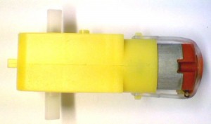
At 6V, these require 120mA running, but stall current can be as high as 500mA


1. Powering Pi & Motors from Same 5V Power Source

This is not recommended.

Pros:

  1. You can use a simple 5V USB power source

Cons:

  1. Pi will suffer when the motor takes excess current. Simply starting the motor could generate enough of a glitch to cause a problem: network interface is likely to be lost first
  2. When the battery voltage gets too low the motors will just go slower, but the Pi will stop and can easily corrupt the SD card
  3. With an inductive load – even using flyback diodes – the spikes on the 5V line can cause serious problems and potentially damage the Pi


2. Powering Pi & Motors from Completely Separate Power Source

This is a highly safe solution – recommended in many scenarios

Pros:

  1. You can use exactly the right power source for both components: 5V USB power for the Pi, any voltage/current source for the Motors
  2. No wasted energy (heat) so nothing gets hotter than it needs to
  3. Can design smaller control boards as no need for voltage regulator, associated components or heatsink
  4. Easier to support as no issues with regulators

Cons:

  1. You need two sources of power 5V
  2. More expensive solution as you need the same batteries as solution 3, plus something like a USB power bank
  3. Heavier solution – small models may not be able to take the 2 sets of batteries


3. Powering Motors from Battery Pack and use 5V Regulator for the Pi

This solution is recommended in some scenarios

Pros:

  1. Only a single battery source needs to be used
  2. Only one battery pack to recharge or switch on and off
  3. Reduces weight and overall product cost

Cons:

  1. When the power gets too low, the Pi will stop and potentially corrupt the SD card
  2. Regulators get hot. At least, linear regulators get hot – switching regulators (see Mo-Pi) are a lot more efficient. Typically 90% or so.


4. How Hot do Regulators Get and Why?

This is the killer question and is the main reason that I recommend using separate power supplies (Option 2 above) in many situations.

Linear regulators take an input voltage (say 7.2V nominal for 6 rechargeable cells) and output a fixed voltage (5V for our Raspberry Pi). To do this, they effectively act as a resistor which automatically varies to keep the output voltage constant. We all know Ohm’s law: V = I x R. The power (heat) of the resistor is easily given as V x I. So if the input voltage is 7.2V, the output voltage is 5V and the current used by the Pi is 0.7A, then the power dissipated by the regulator is: (7.2-5.0) * 0.7 = 1.54W

Now 1.5W doesn’t sound very much, but unless you have some way of dissipating that heat, the temperature will only increase. For small input voltages of 7.2V and less, you may be able to do without a heatsink. However, to dissipate this heat properly you should use a heatsink. We generally use a small one that is rated at 21°C / W. This means that thermal equilibrium is reached at a temperature of 21°C above ambient temperature for every Watt that is dissipated. For the 1.54W above, this means that the temperature of the regulator and heatsink would be 32°C above the ambient temperature. This is warm, but is acceptable and definitely within the relevant British Standards.

The problems come when a) the input voltage is a lot higher than 7.2V, or b) the Pi takes a lot more power than 0.7A. So you should:

  • Keep the input voltage down to something reasonable. We recommend 6 cells of rechargeable batteries as a maximum (ie. 7.2V nominal)
  • Note that the regulator needs some voltage “headroom” to work with. Some require a minimum input voltage of 2.5V above the output voltage (eg. 7805) so that means you have to put in more volts and thus generate more heat. (we use the L4940V5 which has a minimum input voltage of 6V)
  • Do not overload the 5V (or 3.3V) on the Pi with lots of directly powered addons
  • Use a heatsink if planning on using for extended periods (ie. more than a few minutes minutes at a time)

Finally, the power taken by the motors is irrelevant as far as the heat generated in the regulator goes. It will affect the driver chip of course, but that is a different issue entirely and not to be confused.


Adding Shroud to Extended Headers

step05

Why?

Extended headers on Raspberry Pi addon boards are a boon as they allow you to connect additional wires, or even another addon board in some situations. The problem is they tend to be relatively weak and can get bent over easily. Also, it is easy to plug things onto the extension shifted left or right by one or two positions – potentially causing catastrophic failures.

Simon Walters @cymplecy came up with the idea of adding a shroud around the extended header pins. This post shows you how to do it.


How?

Step 1

Take a Raspberry Pi. Any Pi

step01


Step 2

Plug on an Add-On board with extended headers. Here we are using the popular 4tronix PiDie 🙂

step02


Step 3

Take a standard male 26-pin male box header

step03


Step 4

Use a small pair of pliers to pull out all the pins. Pull them from the top upwards.

step04


Step 5

Push the plastic box header shroud onto the PiDie’s extended header pins. Make sure it is pushed all the way down

step05


Step 6

Now you can safely use the extended header pins. Here we plug on a PiGlow from Pimoroni as that uses different GPIO pins (I2C) than the PiDie

step06


Caveat: With the box header I used, it is still possible to put the PiGlow in one pin to the left or right. Maybe there are box headers with less space at either side. However, at least it protects the pins and makes it much more obvious that the extra board is connected wrongly.

Getting to Know Your MicRoCon

MicRoCon – Micro Robotics Controller for Raspberry Pi

Microcon3_01a

This is the baby sister to our full-featured PiRoCon controller board. It still features two bi-directional motor controllers, a 5V regulator for the Raspberry Pi as well as general purpose IO connectors, 5V servo outputs and a 4-pin Ultrasonic input.

Motors A & B

  • Motor A: Pins 24, 26 (GPIO: CE0 and CE1)
  • Motor B: Pins 19, 21 (GPIO: MOSI, MISO)
  • Permanently enabled
  • Use either pin for each motor with PWM
  • Remember to invert the PWM duty cycle when reversing
  • Motors are driven via an L293D H-Bridge chip from the input voltage at the 2-pin terminal (not from the regulated 5V supply)


 GPIO Connections

  • These are NOT level-shifted and only work with 3.3V devices. Do not connect a 5V input
  • Each GPIO pin has an asdsociated Ground and 3.3V pin so can connect 3-pin sensors directly
  • Pin 7 (GPIO: 04)
  • Pin 11 (GPIO: 17)
  • Pin 12 (GPIO: 18)
  • Pin 13 (GPIO: 27)


Servos

  • These 2 sets of 3 pins provide outputs to drive 5V servos
  • The signals are not level-shifted but all servos I have tried work happily with a 3.3V input signal
  • Servo 1: Pin 18 (GPIO 22)
  • Servo 2: Pin 22 (GPIO 25)


Ultrasonic Input

  • These four pins allow an HC-SR04 4-pin ultrasonic sensor to be connected directly
  • This uses a resistor network to allow the sensor to use only a single GPIO pin, which is shared between Ping/Trig and Echo
  • Output a pulse using the pin in output mode
  • Then switch to input mode to await the response
  • This is connected to Pin 8 (GPIO: Txd)


Regulator

  • This uses an L4040V5 linear low dropout regulator
  • The input voltage can go as low as 6V and the output will remain at 5V
  • The higher the input voltage, the hotter the regulator will get in use
  • The motors do not use the regulated voltage so will have no effect on the temperature of the regulator


I2C Female Header

  • Allows easy access to the I2C signals SCL and SDA
  • Also provides 0V, 3.3V and 5V connections
  • Same pinout as used on the PiRoCon expansion header so all expansion boards for the PiRoCon can also be fitted to the MicRoCon – ADC, 16-channel PWM available right now.
  • You can use the 4tronix IP Display dongle directly into this header.


Return to MicRoCon Home

Using the PiDie Raspberry Pi Addon Board

Overview

There are 9 LEDs arranged in a 3×3 matrix:

  • 1, 2, 3 down left side (Red, Yellow, Green – ideal for use as traffic lights)
  • 4 in centre (Green)
  • 5, 6, 7 down right side (Yellow, White, Blue)

These 7 LEDs then form the dots on a dice. The matrix is completed with LED8 (Red – top centre) and LED9 (White – bottom centre)

1  8  5
2  4  6
3  9  7

The Buttons are Red (top left), Green (bottom left), Yellow (top right), Blue (bottom right) and the colours match the colours of the LEDs in the same corners. Ideal for use in the Simon game,


Pin Connections

These refer to the physical pin numbers on the GPIO header. If using gpio module in python, then set the mode to “board”.

LEDs:

  • Led1: 7
  • Led2: 11
  • Led3: 12
  • Led4: 13
  • Led5: 15
  • Led6: 16
  • Led7: 18
  • Led8: 22
  • Led9: 8

Buttons:

  • Red: 21
  • Green: 19
  • Yellow: 24
  • Blue: 26


Use in ScratchGPIO

Download the excellent ScratchGPIO by Simon Walters from here.

  • Create a variable called “AddOn”. In the green flag black, set the variable to “PiDie”
  • The LEDs are named Led1 to Led9
  • To switch a LED on or off, you can send a broadcast message, or use variables.
  • Using broadcasts. Create a new message specifying what you want to happen. The syntax is “Led1On” or “Led1Off”. Change the number to select a different LED:
  • Using variables. You should create variables called Led1 to Led9. You can use the variable setting blocks to switch them on or off:
  • You can also set them all on or all off with a broadcast “AllOff” or “AllOn”


Use in Python

  • Import the GPIO library: import RPi.GPIO as GPIO
  • Set the GPIO mode to board: GPIO.setmode(GPIO.BOARD)
  • Set the LED pins as outputs: GPIO.setup(7, GPIO.OUT) // 7 is the for LED1. You need to do this for each LED, or use lists, etc
  • Set the Button pins as inputs: GPIO.setup(21, GPIO.IN, pull_up_down=GPIO.PUD_UP) // 21 is the for the Red button. You need to do this for each button, or use lists, etc
  • Note that in the line above we are using the internal pullup resistors. This is mandatory for the buttons to work.
  • You can then set an LED On or Off by setting the output to 0 (ON) or 1 (OFF): GPIO.output(7, 0)
  • You can check if a button is pressed with an IF statement: if GPIO.input(21):