Wiring the Unotron with Raspberry Pi and Microcon 3
Click on any image to enlarge.

For the basic mechanical building instructions, please refer to here
Step 1 – Fit the Mounting Pillars

For the Model B+ you should place 4 of the 25mm pillars in the positions shown above. (Note that the one bottom-right in above picture will need the screw removing later to allow the motor to sit properly on the baseplate)
For Models A or B only 2 pillars are required in the positions shown with red ring.
Step 2 – Fit the Raspberry Pi

After screwing in all 4 pillars for the B+, then remove the screw underneath the bottom right-hand pillar so it sites on the baseplate but isn’t screwed in.
Also, note the rubber bumper on the bottom of the mounting pillar of the Microcon v3. This rubber bumper rests onto the PCB of all models (For the Model A and B, you can removed the rubber bumper so the Microcon sits flat with its pillar on top of the mounting screw)
Step 3 – Push On the Microcon v3
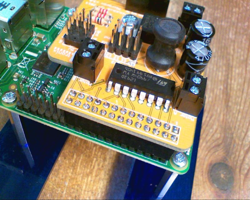
Make sure it is connect correctly to the end of the GPIO connector. For the B+ there will be 14 pins left exposed. For Models A and B, all pins will be covered.
Step 4 – Connect The Motor

Screw in the motor (see instructions for base build here, steps 1 to 7
Depending on the wiring to the motor, you may need to swap the wires so that the software moves forwards and not backwards when required. Check this when first testing the software
Step 5 – Connect the Servo Lead

Plug the servo lead into the position shown (marked 22 on the PCB). Make sure you have this the correct way round with the Black wire next to Gnd, Red wire on 5V and White wire on Sig(nal)
Step 6 – Plug in the Ultrasonic Sensor

Plug the sensor into the breadboard – approximately centred left to right, but it is not critical
Then connect 4 of the 30cm Male-Female wires, ensuring you plug into the same 4 columns of the breadboard as the sensor is in
Step 7 – Wire the Ultrasonic Sensor to Microcon

Ensure that the wires match the signal names printed on the sensor and the PCB. So:
- Gnd -> Gnd
- Echo -> Echo
- Trig (or Ping) -> Ping
- Vcc -> 5V
Step 8 – Wire in the Line Follower Sensors

Again it is important that the voltage is the correct way round. Connect:
- G -> Gnd
- V+ -> +5V
- S -> Sig
The Left sensor should be plugged into the 3 pins labelled 07
The Right sensor into pins labelled 11
Step 9 – Wire in the Battery Pack

Very Important: The positive (Red wire) goes into the terminal marked Vin, and the negative (Black wire) into the terminal marked Gnd. If you get these the wrong way round, you will damage the driver chip.
Testing & Software
You have now completed the wiring of the Microcon onto the Unotron single-wheek robot. Please download the sample code to test it, remembering that you may need to swap the motor wires so forwards is forwards and not backwards. With the Pi powered up and connected to the internet, go into a terminal window (eg LXTerminal) or from the startup terminal if that’s how you run your Pi, then type (or copy and paste):
wget http://4tronix.co.uk/unotron.sh -O unotron.sh
When that is complete, type:
bash unotron.sh
Now you will have a new folder /home/pi/unotron with a library module and examples to try. Eg:
sudo python motorTest.py