Soldering Pi2Go Lite
You can also download a PDF version of this guide here
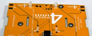
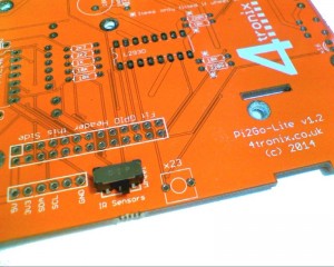
First check which version of the main PCB you have. It is marked above the left motor “Pi2Go-Lite v1.x”. There are minor changes to some parts of the build.
- v1.0 (initial release) – Yellow
- v1.1 (from 20th October 2014) – Yell0w
- v1.2 and later (from 15th November 2014) – Orange
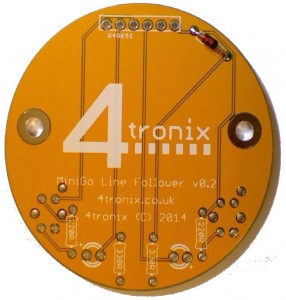
Soldering the Line-Follower PCB
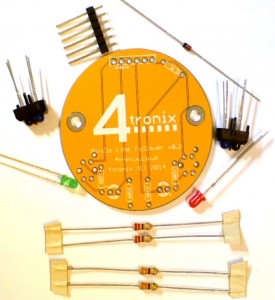
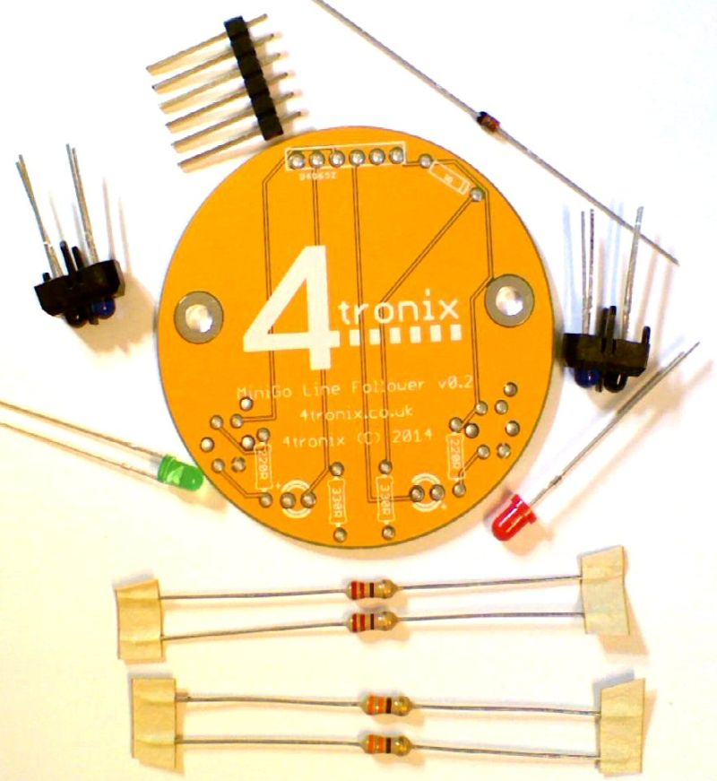
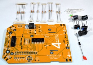
1. Check you have the correct parts
- PCB
- 2 x 330R resistors (Orange, Orange, Brown)
- 2 x 220R resistors (Red, Red, Brown)
- Diode
- 2 x LEDs (Green & Red)
- 2 x IR reflectance sensors
- 6-pin male header
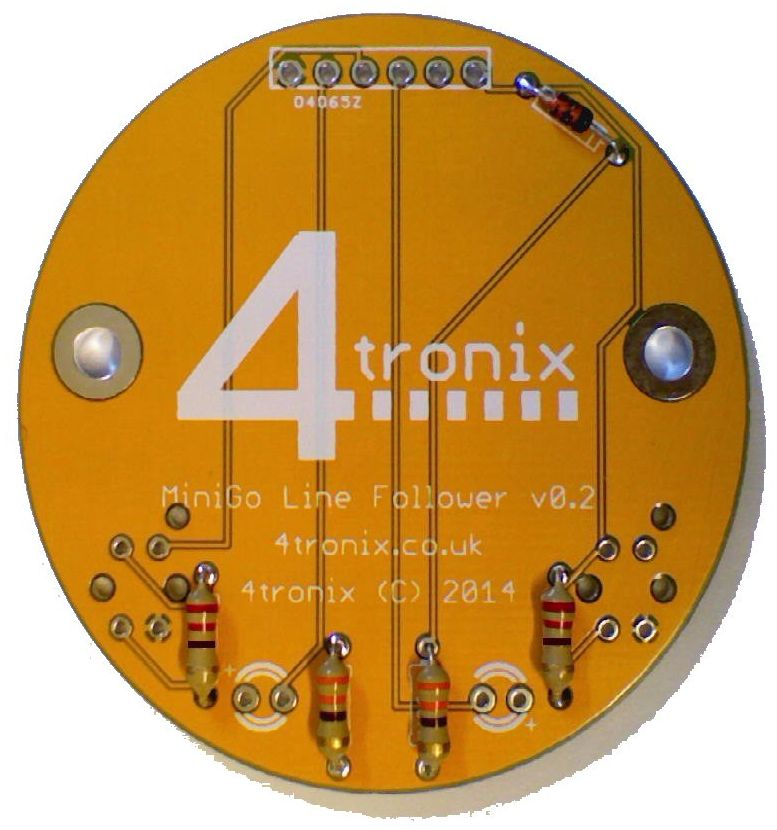
2. Solder the diode – black line away from the connector

3. Add the resistors.
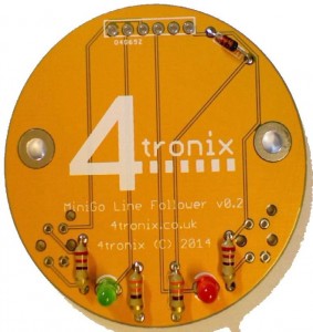
4. Add the LEDs. Long leg next to the + sign on the silk screen (ie. long leg away from centre of PCB)
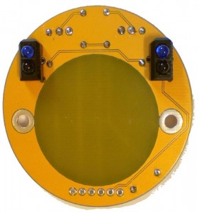
5. Add the reflectance sensors to the bottom of the PCB. Blue LED at the edge of the board as shown
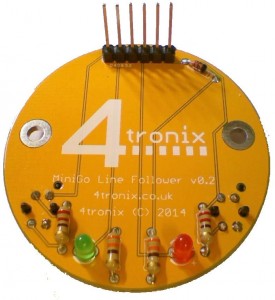
6. Solder the male header to the top of the board. Ensure it is soldered perfectly vertical
Now to solder the main PCB
7. First ensure you have all the parts:
- Main PCB with motor driver, schmidt trigger and voltage regulator fitted
- 4 x 220R resistors (Red, Red, Brown)
- 2 x 330R resistors (Orange, Orange, Brown)
- 1 x 1K resistors (Brown, Black, Red)
- 2 x 2K2 resistors (Red, Red, Red)
- 2 x 10K resistors (Brown, Black, Orange)
- 2 x 56K resistors (Green, Blue, Orange)
- Diode 1N5817
- 2 x 470uF capacitors
- 6 x LEDs (Green, Red, 4 x White)
- 100uH coil
- Ultrasonic sensor
- 2 x IR reflectance sensors
- 2-pin mini tact switch
- Toggle switch
- 3×2 male header (2 of these for v1.1)
- 2 x 6-pin female headers
- 26-pin GPIO header
- 3 x 2-pin screw terminals
- 2 x 0.1″ 2-pin jumpers (v1.1 only)
- 2 x 100nF capacitors – small yellow blobs with long legs! (v1.1 only)
- 1 x miniature slide switch (v1.2 only)
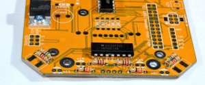
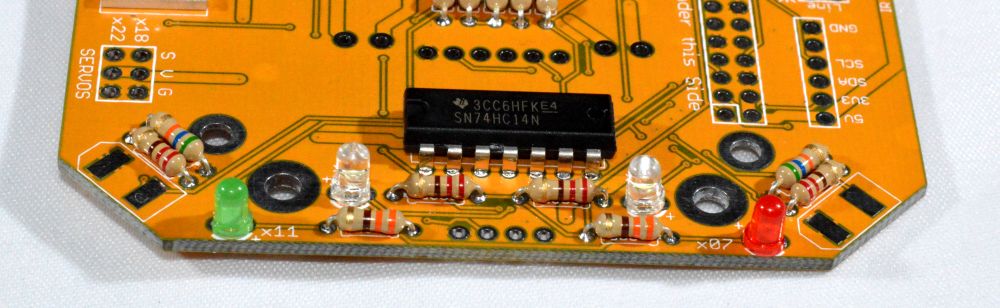
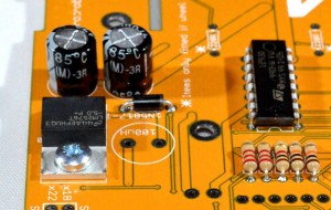
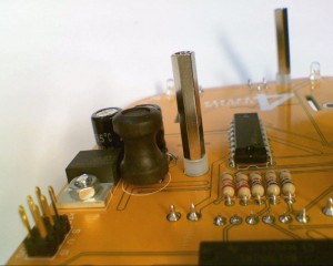
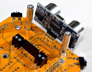
8. Add the resistors near the front of the board. The silk screen shows the value. It doesn’t matter which way they go but it is tidier to keep a standard orientation
** For v1.1 and later, also add the two 100nF capacitors at either end of the IC in photo above
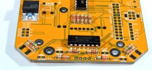
9. Add the resistors in the block near the motor driver chip. For tidiness, keep all the gold bars at the same end
10. Add the 1N5817 diode. Ensure the silver stripe is towards the centre of PCB
11. Add LEDs at front of board. Red is for port (as in the wine), left. Green for starboard, right. And 2 white LEDs.
Ensure that the long lead of each LED goes into the position marked with a + (on v1.0 the + sign has missed the edge of the board and can only just be seen, v1.1 and later are OK)
12. Add the 2 white LEDs at the rear of the board, again ensuring long lead into the +
13. Add the 2-pin tact switch
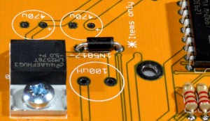
14. Add the two 470uF capacitors ensuring long lead towards centre of board (grey strip on case towards outside of board)
Keep the 100uH coil to one side as it is better to leave this until last as it is quite tall
Now open the bag of headers and switches:
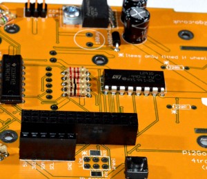
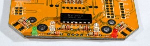
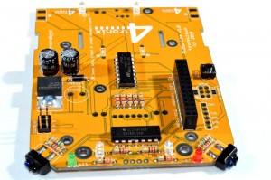
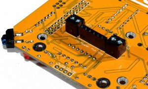
15. Add the three headers:
- 6-pin female header for I2C breakout (bottom left of photo)
- 3×2 male header for servos (top left of photo)
- ** For v1.1 also add a 3×2 male header in the position at the bottom centre of above photo
- 26-pin GPIO header
- For v1.0, note that the lower 3×2 header is not used unless the wheel encoder add-on pack is fitted
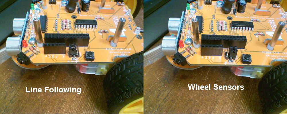
- ** For v1.1 add the 2 blue jumpers in the leftmost positions for line followers, or rightmost positions for wheel sensors
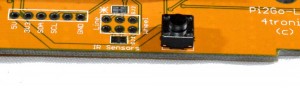
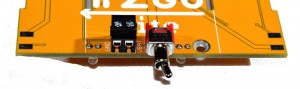
- ** For v1.2 we have replaced the 3×2 headers and 0.1″ jumpers with a miniature slide switch as shown below
The position of the jumpers (v1.0 and v1.1) should be as shown below. Put both jumpers to the left for line following, and to the right for wheel sensing. Note that the jumpers should be aligned along the length of the Pi2Go-Lite, not across the board.

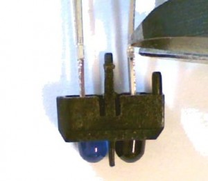
16. Snip the 4 leads on each reflectance sensor at the position shown
17. Solder the sensors in the front corners. Ensure you solder the top and the bottom of the board and that the blue LED is to the left as looking at the photo above
Note: If you are using the wheel sensors, now is a good time to head over to the build instructions for wheel sensors
18. Add the three 2-pin terminals to the bottom of the board. Connector holes should face to the rear of the board as shown above
19. Add the 6-pin female connector to the bottom of the PCB. Ensure that it is mounted perfectly vertical as it is used to connect to the line follower board. Solder one pin, then adjust the position with one hand whilst keeping the solder melted with the other. 3 hands helps here!
20. Add the toggle switch to the underside of the PCB at the rear. This is the On/off switch
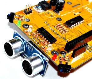
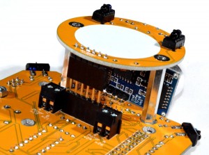
21. Solder the ultrasonic sensor board to the bottom of the board, facing forward. Ensure it is fully inserted and horizontal.
NOTE: Sometimes we receive a batch of ultrasonic sensor modules where the header is on the same side as the sensors. Do NOT fit these. Contact us immediately for a replacement. If these are fitted, they will interfere with the mounting pillars and may cause a short-circuit.
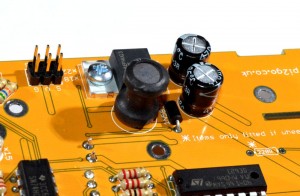
22. Finally solder the coil in place
The PCB is now fully soldered.
Soldering the Motor Wires & Capacitors
Notes – Please read:
- It is very important to add at least one capacitor between the two terminals of each motor. This removes about 70% of the electrical noise produced by the motor. Another 20% can be removed by adding 2 capacitors, one from each terminal to the case. This is trickier to do, so leave off if you are not sure about it. When we solder the kits, we add all three capacitors as shown below
- The Red wire and Black wire should be connected as shown, or the motors may run backwards in the example scripts
Motor Step 1 – Identify the Parts
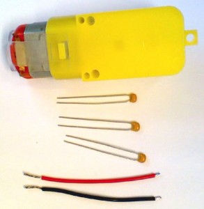
For each motor we provide 1 capacitor, a red 5cm lead and a black 5cm lead. You can optionally add 2 more capacitors for that extra noise reduction
Motor 2 – Add Main Capacitor
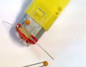
Feed a capacitor through the metal terminals and solder as shown. It doesn’t matter which way round it is fitted.
Then clip the leads short – being careful not to clip off the motor terminals
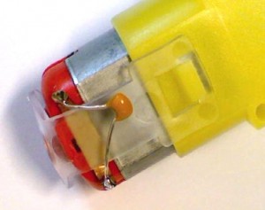
Motor 3 – Add Second & Third Capacitors (Optional – not provided)

If required, the other 2 capacitors should be soldered between one motor terminal and the metal case, as shown above. You will need a hot iron to heat up the case sufficiently to melt the solder. Also, the motor case can become oxidised over time making it very difficult to solder to. Some “wet and dry” sand paper can be used to brighten up the metal if required.
Then clip the leads short:
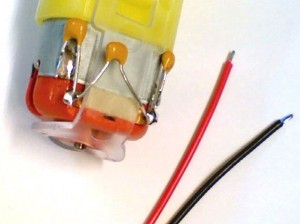
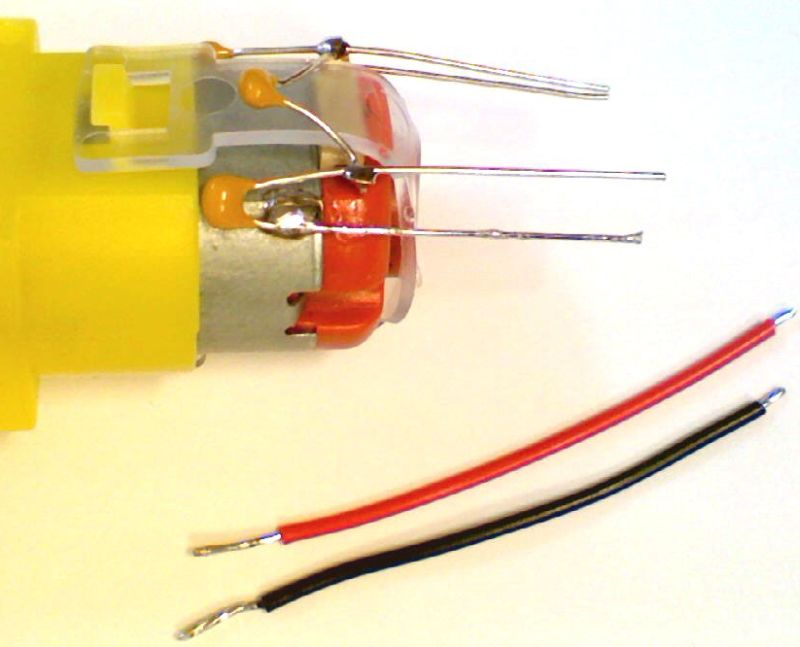
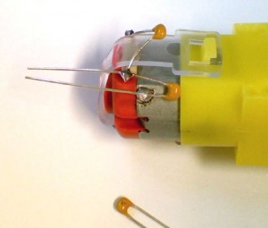
Motor 4 – Add the Wires
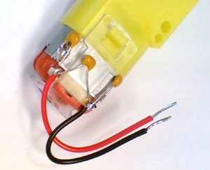
- Each wire has a short end and a long end. The short end should be soldered to the motor
- Solder the Red wire to the top terminal and the Black wire to the bottom terminal, as shown above. If you solder them the other way round the Pi2Go-Lite will run backwards.
Assemble the Pi2Go-Lite
You could watch the one minute assembly video here but note that some things are slightly different from this released version
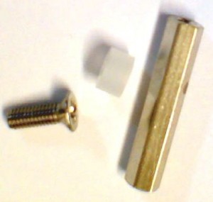
For each Raspberry Pi mounting position you will need a 20mm M2.5 pillar, an 8mm countersunk screw and a 3mm spacer.
For the Model B you will require 2 sets, and for the Model B+ you will require 4 sets
Here we have mounted 2 pillars in the correct positions for a Model B. Screw the countersunk screw through the PCB from the bottom, through the spacer and into the 20mm metal pillar.

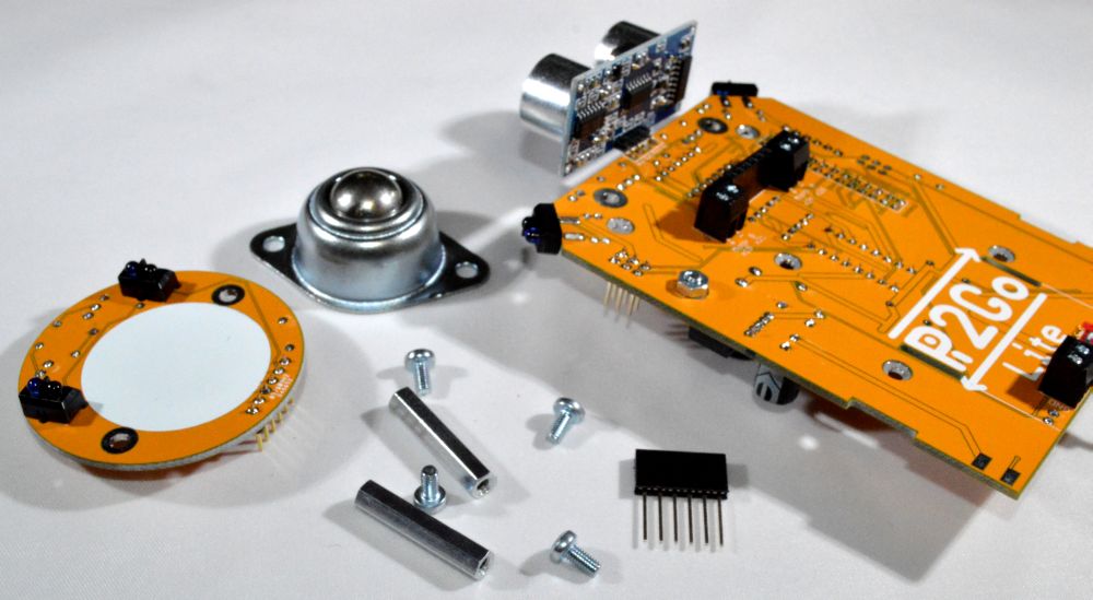
Prepare the line follower PCB, the 4 M3x6mm screws, the 2 M3 25mm pillars, the ball caster and the 6-pin female header
Screw the 25mm pillars into the main PCB using 2 of the 6mm M3 screws
Push the female header onto the male header on the line follower board, then push the completed assembly into the female header on the underside of the main PCB. The holes in the line-follower PCB should then line up with the pillars and the line follower board should lie flush with the top of the pillars
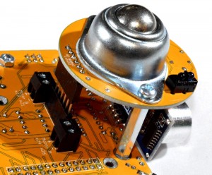
Use the 6mm M3 screws to screw through the ball caster, through the line follower PCB and into the pillars
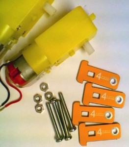
Prepare the items required to mount the motors:
- 2 motors with wires and capacitors ready soldered
- 4 motor mount PCBs
- 4 M3x25mm screws
- 4 M3 nuts
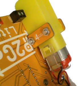
Push the motor mount PCBs from the top of the main board so that the holes line up with the mounting holes in the motor. Pass the 25mm screws from the outside, through one mount, through the motor and then through the second mount. Screw into the M3 nuts on the inside. Repeat for both motors.
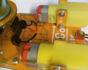
Red wires should be screwed into the terminals marked with a +, and the black wires into terminals marked with a -. This gives a Red – Black – Red – Black arrangement
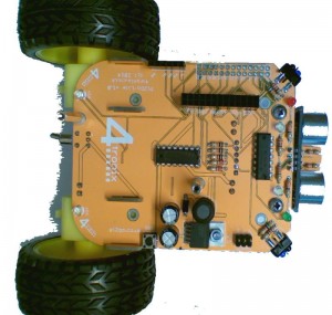
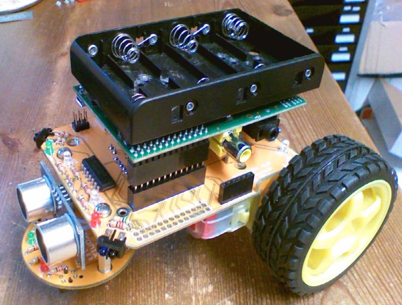
Push the wheels on now as it makes the unit more stable. Your Pi2Go-Lite should look like this

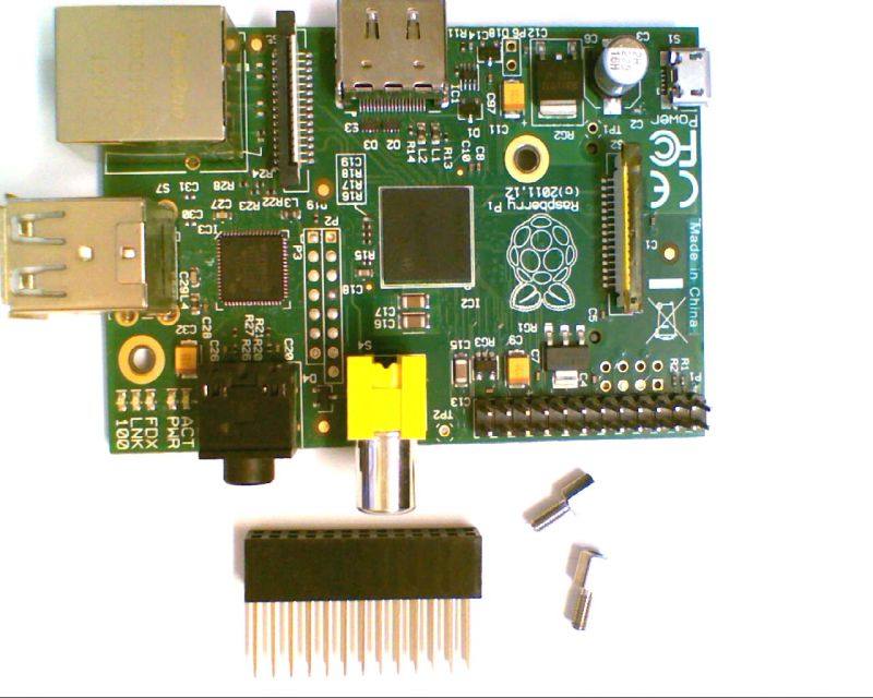
To mount a Model B you will need an extended GPIO header and 2 x 5mm male-female pillars.
To mount a Model B+ you will need also need 2 x 4mm countersunk screws. For the B+ use the screws for two front mounts and the 5mm male-female pillars for the two rear mounts.
Above: Model B mounting
Below: Model B+ or RPi 2B Mounting (2 x 5mm pillars at the rear)
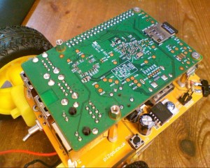
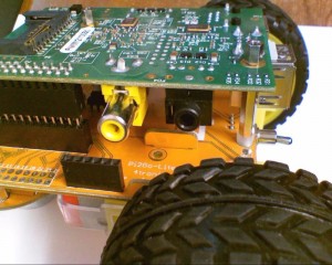
Push the extended header into the GPIO header on the main PCB, then carefully push the Raspberry Pi onto the extended header. Ensure that the mounting holes in the Pi match the pillars. If not, check that the GPIO header is plugged into the correct position.
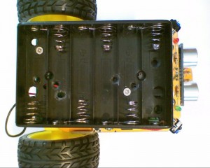
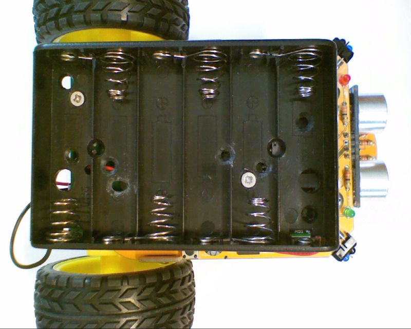
Above: Model B Battery Holder Mounting
Below: Model B+ or RPi 2B Battery Holder Mounting
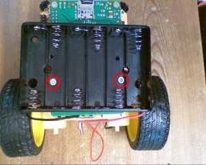
Now use 2 4mm countersunk screws to fit the battery holder into position, screwing into the 5mm male-female pillars that hold the Pi. For the Model B, the battery holder is mounted as shown above. For the Model B+ it is mounted cross-wise near the rear of the unit and offset, to allow access to the 6-pin I2C breakout header
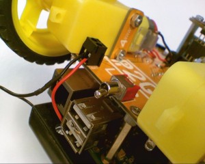
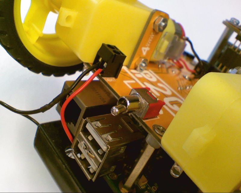
Fit the red wire from battery holder into the position nearest the switch – marked VBAT. The black wire goes into the position next to the motor.

Your Pi2Go-Lite is now Complete!