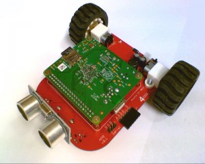
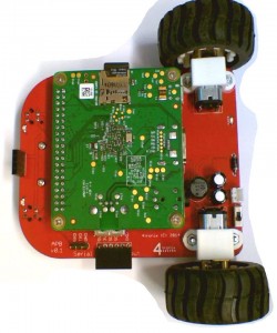
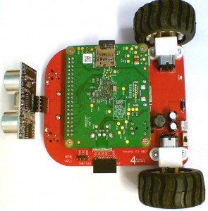
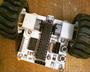
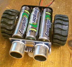
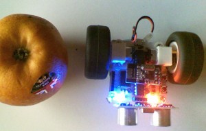
Agobo Robot for Raspberry Pi Model A+ (APB)


AGoBo is the winning name – Suggested by @mcambelluni

Mark will receive a complete AGoBo prototype, as well as the next iteration of the main PCBA.


abp02

Starting 29th November 2014 and finishing 1st December, we are running a Twitter based competition to choose a product name for this new robot, codenamed APB01


The winner will receive a complete prototype robot, including the Model A+ and we will ship it worldwide.


apb03

apb04


Specification

This is a prototype robot at the moment, and we expect the specification to change before we start selling it in January. Current specs as follows:

  • Supports Raspberry Pi Model A+ only
  • Size 100 x 80 25mm (excluding wheels)
  • Built-in power supply that works from 6.6V to 12V quite happily, supplying power to both the robot and the Pi
  • Serial connections (for SSH console cable) brought to convenient connector on the edge
  • Standard 4tronix 6-pin I2C breakout connector – direct fit for the IP Display module we make
  • 2 x line follower sensors with indicator LEDs
  • Ultrasonic distance sensor
  • N20 size, metal geared motors
  • 42mm wheels
  • Provided ready soldered. Just screw in your Pi and add batteries.

It really is as easy as Pi to get going in robotics now.

Competition entries (in order of appearance)

  1. mA+rvin – @MarkSwashplate
  2. Colin – @newsliner
  3. Pi2Go Nano – @monkeymademe
  4. Pi2Go mini – @monkeymademe
  5. Eric – @Mruktechreviews
  6. Ratbot (rA+bot) – @monkeymademe
  7. picabot – @TommyBobbins
  8. nitbit – @monkeymademe
  9. berryBot – @monkeymademe
  10. HatBot (hA+bot) – @monkeymademe
  11. DiddyTron – @AverageManvsPi
  12. DiddyBot – @AverageManvsPi
  13. A+ PiBot nano – @BitSkils
  14. The Crumb – @AverageManvsPi
  15. The Mighty Maus – @heeedt
  16. PiBotA+ – @skinnermartin78
  17. GoA+Bot (GoAtBot) – @skinnermartin78
  18. NanoGo – @skinnermartin78
  19. Johnny – @Ascii211
  20. MadgeBot – @ukscone
  21. BiBot – @JarrowComputing
  22. DinkyBot – @skinnermartin78
  23. MidiBot – @skinnermartin78
  24. +SonicBot – @CoderDojoCarm
  25. BotAplus – @treefrog52
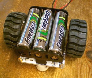
  26. BotAppi (BotA+Pi) – @AndyBateyPi
  27. A4 – @sej7278
  28. A Robot – @sej7278
  29. PiBot – @TeCoEd
  30. Alfie – @richard007_1999
  31. AtBot (A+Bot) – @uk_baz
  32. Flat Stanley – @uk_baz
  33. 4tA+v1 – @uk_baz
  34. HalfPint – @skinnermartin78
  35. Swarmer – @zosho
  36. NA+Bot (NatBot) – @skinnermartin78
  37. Pip – @skinnermartin78
  38. BitBot – @skinnermartin78
  39. DotBot – @skinnermartin78
  40. A+Go – @skinnermartin78
  41. A+GoBot – @skinnermartin78
  42. Rudolph – @CoderDojoCarm
  43. RaspAÏ€bot – @skinnermartin78
  44. JittyBot – @JarJarGeek
  45. Pi-onic – @red_dragon25
  46. PocketBot, PocA+Bot – @skinnermartin78
  47. PiAbot – @RobertsDavidJ
  48. PiAtron – @RobertsDavidJ
  49. PintBot – @recantha
  50. AGOBO – @mcampbelluni
  51. PiAGoGo – @mcampbelluni
  52. KinderBot – @APChristie
  53. SchoolieBot – @APChristie
  54. IKnowBot – @APChristie
  55. DeBug – @RobertsDavidJ
  56. aRobot – @Stimmli
  57. rA+pless (ripless) – @MBDilaver
  58. PiPlusBot – @Cloud4Schools
  59. RoboPip – @StefanPlum
  60. piDestroyer – @evgeniyraev
  61. pupPi- @evgeniyraev
  62. HAL 1- @evgeniyraev
  63. a1- @evgeniyraev
  64. Dalek- @evgeniyraev
  65. BugPi – @skeletony
  66. BuggyPi – @skeletony
  67. PiAGo – @skinnermartin78
  68. PiAGoBot – @skinnermartin78
  69. FrogBot – @AndyBateyPi
  70. PiFrogBot – @AndyBateyPi
  71. Piccolo – @ukscone
  72. amphipian – @AndyBateyP
  73. ampibot – @AndyBateyP
  74. apphibian – @AndyBateyP
  75. appibian – @AndyBateyP
  76. MidiBot – @skinnermartin78
  77. MidiTron – @skinnermartin78
  78. Medius – @skinnermartin78
  79. 4tronix build BotAplus – @treefrog52
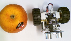
 

Finalists (in Order)

  1. AGOBO – @mcampbelluni WINNER
  2. Piccolo – @ukscone
  3. NanoGo – @skinnermartin78
  4. mA+rvin – @MarkSwashplate
  5. Pi-onic – @red_dragon25
  6. BotAppi (BotA+Pi) – @AndyBateyPi
  7. HatBot (hA+bot) – @monkeymademe
  8. BotAplus – @treefrog52
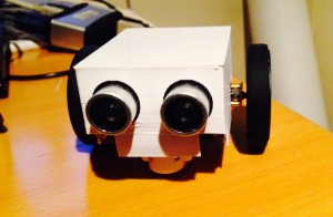


Soldering the UltraSonic & LED PCB Kit

UltraSonic & LED PCB Kit

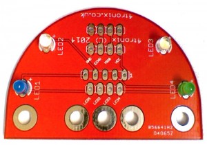
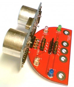
This kit makes it easy to mount a standard SR-HC04 ultrasonic sensor on the front of a robot. The sensor itself is soldered to the PCB which acts as a carrier, additionally having M3 mounting holes at various spacings.

The board also carries 4 LEDs with the necessary series resistors to be driven directly from Arduino or Raspberry Pi GPIO pins.

Click any image to enlarge.


1. Check you have all the parts

ultra01

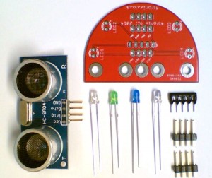
The kit contains:

  • 1 x PCB
  • 1x UltraSonic sensor
  • 1 x Resistor pack (4 x 220R resistors in a SIL package)
  • 2 x White LEDs
  • 1 x Blue LED
  • 1 x Green LED
  • 2 x 4-pin male headers


2. Solder the LEDs

ultra02

It doesn’t really matter where you put each LED, but the standard way for our Pizazz robot is as shown above.

NB. Ensure that the longer lead (positive) from each LED is soldered into the holes marked with a ‘+’ sign (towards the top of the board in the photo above)


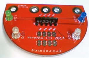
3. Solder the Resistor Pack

ultra03

The resistor pack must be placed the correct way round, with the white dot next to the ‘1’ marked on the PCB. The writing is therefore point towards the ultrasonic mounting points as shown in the photo above.


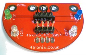
4. Solder the 4-pin Male Headers

ultra04

These should be mounted in the positions either side of the resistor pack. To get the straight, I find it easiest to solder just one pin of each header, then holding the board and header in one hand and the soldering iron in the other, gently melt the solder and move the header so it is straight. There’s a bit of a knack to this 😉


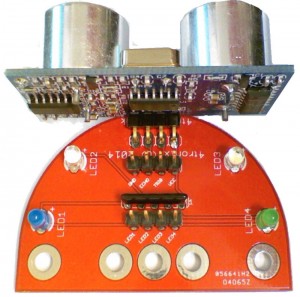
5. Finally, Solder on the UltraSonic Sensor

ultra05

This should be mounted on the same side as all the other components. You can double check, by checking that the writing on the front of the sensors, matches the pins on the 4-pin header next to it. (ie. VCC is next to VCC, Trig is next to Trig, etc)

Again, solder one pin first then straighten it out using the same method as for the headers.


6. The Completed Board – Ready for Mounting on your Robot

ultra06


First Information for Picobot – Swarm Robots perhaps

Some early Info About the Picobot Robotics Project

pb01


I’ve been working on and off for a while on a small robot because:

  1. I want to make available a really cheap programmable robot for schools
  2. I would like to make one that can communicate with other robots, detect them and interact with them
  3. If they can be made cheaply enough then making a swarm of 10 or more becomes feasible

pb05

pb02

pb03

pb04

pb07

pb06

pb09

case01

pb10


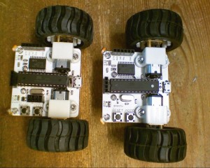
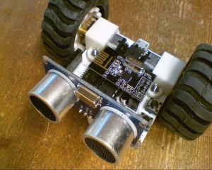
This version of Picobot (V2) contains a small number of sensors as well as a connector for an NRF24L01 2.4GHz RF module. This is stupidly cheap RF module with a reasonable range and excellent support in the Arduino community.

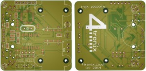
  • Dimensions of PCB 50 x 50mm
  • Motors: 2 x N20 size with 70:1 reduction gears
  • Wheels: 42mm diameter
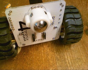
  • Front ball caster
  • ATmel ATMega328P -PU(DIP) controller chip with Arduino bootloader
  • Interface to CP2102 USB-serial converter (with auto-reset). Only one converter required for all your bots, no need to waste money (and board space) having one for each
  • Plug in socket for HC-SR04 ultrasonic distance sensor
  • 2 x LDR for light level sensors
  • Reset switch
  • Mode select switch (use in your programs how you like)
  • Micro-USB for power only – will work from 3.7V to 5.5V
  • On-Off switch


Next Revision is V3 – Updated Info

V3 adds the following – keeping the PCB the same size

  • TQFP package for the ATMega328P-AU (smaller, surface mount)
  • 2 x IR line follower sensors
  • 2 x RGB LEDs underneath at front
  • Rear bright white LED, used for follow-the-leader swarming
  • Change to use of 2-pin JST connector for direct powering from 3.7V Lipo battery
  • New, thinner 47mm diameter wheels

Picobot_04c