
Links
Brief Description of all new blocks
Overview
The latest incarnation of the hugely popular BitBot is the new BitBot PRO, with on-board processor providing intelligent and accurate motor control, with sensor resolution of over 100 pulses per centimetre. Driving straight has never been so easy.
We’ve also taken the opportunity to upgrade and improve many other features; including the sounder, the line follower sensors and even the power supply circuit – as well as adding several extra mounting holes for you to fix your DIY updates. Finally, there is an infraRed receiver to enable simple remote control using the 4tronix InfraRed remote controller (optional extra) – note that the remote control is not paired to any particular BitBot PRO, so all nearby units in line of sight will receive the same commands.
Python Programming
We will be writing a separate article to cover programming in micro-python. In the meantime, our customer Brecht Willems has kindly allowed us to share his work here: https://github.com/BTWS2/bitbot_pro
Makecode Programming
Of course, we have also updated the Makecode Extension to support all the new features:
- New blocks for accurate movements of the wheels; motion in a straight line by a selected distance, spinning a determined angle and even moving in an arc of a user-define radius and angle. You can also read back the distance and angle moved.
- New blocks for both Digital and Analog line sensors, as well as enabling user or automatic adjustment of threshhold values. Finally a merge of all the line sensors to give a single value estimating where the line is, from -100 for on the far left, through 0 in the centre to +100 on the far right.
- New blocks for the sounder to support changing volume, pitch and duration. Note also that the sounder can now use the Makecode Music blocks as well
- New blocks for the InfraRed receiver: event driven blocks that are run when specific keys are pressed, as well as being able to test the last key pressed
Motor Control
The new motors used in BitBot PRO are small metal-geared motors with a nominal speed of 155 rpm at 6V and a gear ratio of 100. On the back of the motor is a black magnetic disk which provides about 100 pulses per revolution of the wheel. The onboard software uses these pulses to work out how far each wheel has travelled and when to speed up or slow down and stop so that the correct number of pulses has been counted when the command has finished. This allows for much more accurate straight line movement as well as accurate distances and angles.
The existing (pre BitBot PRO) commands for the motors still work and, in most instances, they now allow for “straight line” driving automatically using the PID control loop (see below). It is important and useful to note that the “move … motor … ” block shown below does not use the straight line control and will drive motors using the normal method.

In the “Motors” section of the new Makecode Extension for BitBot PRO, there are several commands for selecting a specific movement. These are mostly self explanatory. Here are a few examples
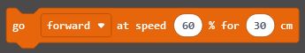
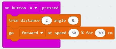
This command allows you to select the direction (forwards or reverse), the speed (0 to 100) and the distance to travel in centimetres
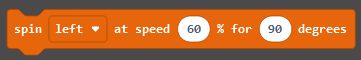
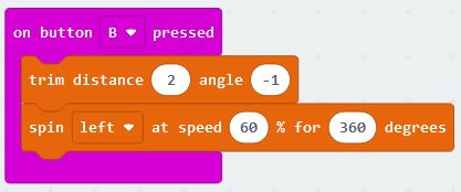
This command lets you spin on the spot to the left or right, at a selected speed (0 to 100) and for any number of degrees.

Then you can combine these two commands in a loop and very simply draw an accurate square.

In fact, just by changing a couple of the numbers you can draw any regular shape. This one is a hexagon. We’ve changed the number of iterations of the loop to 6 (number of sides we want) and the angle turned each time to 60 degrees (360 divided by number of sides)

Moving in an arc is managed by the BitBot PRO calculating the required speed of each motor and the distance each motor has to travel to move the number of degrees required at the radius set. If you do an arc of 360 degrees, you will have drawn a full circle.
PID Control
The control software for the motors is called a PID Control Loop. The PID acronym stands for Proportional, Integral, Derivative and refers to the three elements that define how far each motor is from the correct speed, distance and acceleration. This function can be turned off and then you get the standard motor control you have used in the past. It is very important that you do turn off the PID control if you are doing a lot of rapid changes to the motor speeds – such as for some line following programs or reacting to distance sensor changes. The PID control only works if it is given time to speed up and slow down.
The PID control loop is a complex algorithm that essentially does three things:
- Tries to keep both motors going at the selected speed – starting slowly and accelerating to reach the selected speed (soft start)
- Tries to keep both motors going at the same average speed so that the distance covered by both motors is the same
- Stops the motors when they have reached the selected distance
Because the speed ramps up to the selected value, starting the command repeatedly will keep resetting the speed back to the starting value. This potentially means that the motor will never actually start moving (depending on battery levels, friction, etc)
Even if you give it enough time to get moving between starting new commands you may find that the overall path is not straight. This is because there hasn’t been enough time to stabilise both motors
Because of these two issues, we strongly recommend switching off the PID control if you are repeatedly setting new movement commands.
Line Following
To create line following tracks, we recommend the Robot Square tracks that you can download from https://4tronix.co.uk/files/linefollowtiles.pdf
These should be printed clearly on a laser printer. We use these track elements as our test tracks, so we are confident these will work well.
There are several improvements added to the BitBot PRO beyond earlier versions of BitBot. We have added an extra, central, sensor and all the sensors are now Analog although we have provided both Digital and Analog Makecode blocks. We have also added a block that merges all line sensor blocks into a single “line position” number from -100 for far left, to +100 for far right. Now we can code several methods/algorithms for line following programs:
Classic Digital Sensor Line following:
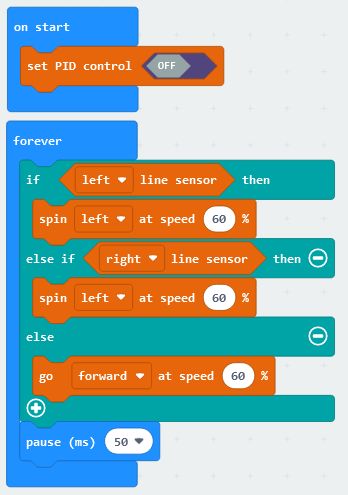
This method simply drives forward if no line sensor is active, or spins left/right if the associated sensor is active. You may need to adjust the speeds and pause values for the best results. It typically results in a successful, but rather jerky, movement.
Classic Analog Sensor Line Following:

This method sets the speed of each motor to be proportional to the related sensor. The line sensor can have values from 0 (perfectly non reflective) to 1023 (perfectly reflective), but the motors require values from 0 to 100. Therefore we need to adjust the values – the numbers shown may not be the best that you can achieve, so you should check the values you actually receive on your line following mat/drawing/printout and scale the numbers accordingly so that the white area gives 100 and the black area gives 0. It results in a very smooth line follower.
New “Merged Value” Line Following:
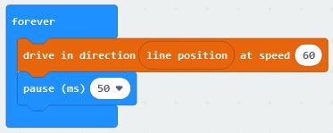
The new, merged value, “line position” block can be directly combined with the new “drive in direction…” block to produce an extremely simple and smoothly operating line follower program. The “drive in direction…” block requires a direction from -100 for turn left, through 0 for go straight, to +100 for turn right. These are the same values that the “line position” block produces. As this is all done “behind the scenes” it doesn’t necessarily produce the most reliable or fastest line follower. As with all of these line follower examples, if you go too fast then you will drop off the line.
InfraRed Receiver
The BitBot PRO has an integrated infrared receiver at the front, next to the accessory connector. However, the Infrared remote control handset is not included to save cost as not all customers will want it. It is available as an optional extra.
The IR receiver is very easy to use in your program. You can set up as many different event blocks as you need; one for every key on the keypad if you want. Each event block will be run when the selected key on keypad is pressed. You can also have an event block that is triggered by any of the keys being pressed, then decide in the block what to do based on the specific key that was pressed. This is useful in some scenarios.
Note that the keys on the keypad are labelled with numbers and symbols, but you can use them to do whatever you need. There is no specific mapping between the keys on the keypad and what you do with that information in your program. You could use the “up arrow” key to spin 90 degrees left if you want.
Note also that there is no pairing between the infrared keypad and the BitBot PRO. Any BitBot PRO that “sees” the message from the keypad can respond to it. This is great if you want multiple BitBot PROs to start dancing at the same time for instance. On the other hand, in a classroom environment you probably don’t want all the BitBot PROs to be controlled from a single keypad. It isn’t really that bad though, because the keypads are fairly directional and the range isn’t very far, so you could point the keypad at a particular BitBot PRO and reasonably expect only that one to respond.
This is an example of a single key triggering an event block:

Here we have selected the “Up arrow” and when that is pressed, a Rainbow display is shown on the Fireleds and the BitBot PRO moves forward 30cm
In this example we trigger the block on any key being pressed, then check inside the block to see which key was actually pressed:

We select the “any” key and then use if..then blocks to run the options. This allows us to do something that is common to all the functions in just the one place – in this case, “set led rainbow”. You can also use the “if key was pressed” blocks within a loop to exit – for instance, in one of the line following loops to stop it moving.
All *New* Blocks Described briefly
Motors
Starts BitBot PRO moving forward or reverse at a speed from 0 to 100% of full speed. It will travel the distance specified and then stop. Both the distance and the speed can be negative, so going forward at -60% speed will actually move in reverse. Note that full speed is less than on BitBot XL for two reasons: 1) The motors are more highly geared, and 2) the PID control algorithm requires some “head room” to ensure both motors can go at the same speed
Starts the BitBot PRO spinning on the spot left (anti-clockwise) or right (clockwise). The speed can be from 0 to 100% of full speed. Both the speed and the number of degrees can be negative, so spinning left at -60% speed will spin right, for example

Calculates the different speeds required for each motor, based on the radius and the nominal speed. Keeps moving until a stop or other motor command is issued
Calculates the different speeds required for each motor, based on the radius and the nominal speed. Stops after the selected number of degrees has been turned. The angle turned can be negative as well as positive. Negative angles will turn clockwise, positive angles will turn anti-clockwise

This block does not use the PID control. The direction can vary from -100 to +100. It drives each wheel individually so the BitBot PRO turns sharp left when the direction is -100, goes straight when direction is 0 and turns sharp right when the direction is +100. For intermediate directions, it will curve to the side at a shallow or steep curve depending on the direction. This block can be used on its own, but it is mainly expected to be used with the “line position” block to implement a simple line follower

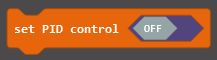
If your program is rapidly changing the speeds or directions of motors, such as in a line following program, you don’t want the PID control software to keep trying to control the motors. Use this block to switch off the PID control, or switch it back on again

This block returns the distance moved by the selected wheel (or the average of the two) since the last reset of the sensor count. You can see the result as millimeters, centimeters, inches or pulses. Moving forwards will increase the count and reversing will reduce the count. This counts at the same rate as the system counter used in the PID control, but is not the same counter because resets will occur at different times

This block gives the angle turned in degrees since the last reset of the sensor counts, based on the difference between the left and right wheel counts

This block will reset to zero the counters used in the distance and angle turned blocks above
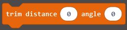
This block should rarely be used and when used must be used carefully. Because of manufacturing tolerances on the wheel diameter and wheel spacing, it may be that the BitBot PRO does not move or turn exactly the correct distance. This block allows you to make small adjustments to the default constants used internally to calculate movement distances and angles. Setting both the distance and angle trims to 0 will return the constants to the factory default values. Setting them positive will make the BitBot PRO travel further or turn a larger angle. Setting them negative will shorten the distance or reduce the angle. Both trims can have values from -100 to +100 and the maximum values will change the distance by about 20%. See the trouble shooting section for more details.
EEROM

This block allows you to store a byte value into the user area of the EEROM. The bytes are addressed from 0 to 200. This data is stored permanently in the BitBot PRO, even if the power is switched off or the batteries removed. You could, for instance, use it to store a sequence of moves that are checked in your program when it starts to determine where the BitBot PRO will move
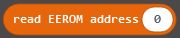
This block reads the value stored in the address specified in the user area of the EEROM. The value is a byte which is interpreted as -128 to + 127. The address can be from 0 to 200
Line sensors

This block provides the analog value (0 to 1023) of the selected line sensor. There are three line sensors on the BitBot PRO, which are sensitive to infrared reflected off the surface below. A totally non-reflective surface (in complete darkness) would give a value of 0, whereas an extremely bright source of infrared would give a value of 1023. Typical values for a laser printed line on photocopier paper are about 180 for the white paper and 70 for the black line – but these values can vary greatly. Also be aware that any source of infrared light (eg. sunlight through windows or torches) can cause the reading on the sensors to be higher

This block returns “True” if the selected sensor recognises a black line, otherwise it returns “False”. It can be used directly in an If..then..else block. The internal software checks the analog value from the sensor against a threshold and a hysteresis value (guard band) to determine if the value is a black line or not. You can set these values if required using the next two blocks
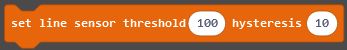
This block sets the threshold and hysteresis (guard band) values for all the line sensors to the values given. The factory default settings are 100 and 10 as shown above. These values are stored in the system area of the EEROM so will be valid even after switching off and removing batteries etc

This is another block to allow setting the threshold and hysteresis values for the line sensors. In this case it causes the BitBot PRO to enter a special routine that will sense the reflective and non-reflective surface below, then set the threhold and hysteresis values separately for each sensor. The process is as follows:
- Sets the front two FireLeds on each arm to Red
- Waits until it detects a reflective (eg. White) surface below on all sensors, then sets the front two FireLeds on each arm to Orange
- Then move the BitBot PRO by hand over and off a black line five times, making sure all wheels and the front caster stay on the surface so the distance to the sensors is constant.
- As you move the sensors over and off the line you will see the indicator LEDs for each sensor go on and off.
- When it has done this five times on all the sensors the front FireLeds are set to Green for 2 seconds
- Finally, the front 2 FireLeds on each arm are set back to their original colours and the process is ended. The new data is saved in the system EEROM
Power

This block gives the battery voltage on the BitBot PRO in volts. Note that the value will be lower if the motors are moving or the FireLeds are on bright. Also note that alkaline batteries will give a higher voltage than rechargeable batteries. So ensure that you compare under similar conditions if using this to determine whether the batteries need changing or not
InfraRed
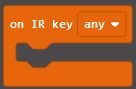
Use this event block to run some specific code when the selected key is pressed on the InfraRed remote control keypad. You can have as many of these event blocks in your program as you like, as long as they all use different IR keys. You can also select the “any” key as shown above. This event will run when any of the keys on the keypad are pressed. However, when any other IR events will run as well is a lottery as it depends on the order they are checked, so it is best to not use any other IR events if you use the “any” key

In some situations you may not want to run a separate block of code when an InfraRed key is pressed, but you still want to know if a certain key has been pressed – maybe if you want to stop doing something if the “stop” button is pressed. Then you can use and if..then block to check a specific (or any) key is pressed and act accordingly

This block just returns the key code of the last IR key pressed. You could then compare it with a specific key (from the block below, for instance) or a particular value

This block gives the key code of the selected key. You can use it to compare against the last IR code pressed (see the block above) to see if that key was pressed
Trouble Shooting
As we are trying to produce, across thousands of units, accurate distances and angles essentially via dead-reckoning, it is likely that manufacturing tolerances will creep in and cause inaccuracies in movement. Don’t worry, this can be easily resolved.
Inaccurate Distance
The distance moved is determined by the diameter of the wheels and the number of pulses on the sensors. The diameter can be different from the nominal value due to manufacturing tolerances. In addition, the wheels may slip on the surface being used, or there could be a build up of dirt on the wheels.
You can correct for any deviation by setting the distance “trim” appropriately. Note that a trim of 0 is the factory default value.
If you ask the BitBot PRO to move 30cm and measure the distance to be higher than this, then set the trim to a negative value. Alternatively, if it actually moves a bit less than the desired distance, then set the trim to a positive value. Once you have set this value, you shouldn’t have to do it again because the trim value is stored permanently in the EEROM on the BitBot PRO.
In the test below we have found that setting the distance trim to 2 gives an accurate distance travelled. Now we can move on to making the angle turned more accurate.
Inaccurate Angle
The angle turned is very sensitive to the actual distance between the wheels. It also depends on an accurate distance measurement, so you should always trim the distance value, before setting the trim for angles.
Mechanical Fix
The wheels used on the BitBot PRO have an outer stop so that they can’t be pushed on too far. However, the actual distance between the wheels can vary because of several mechanical factors. If the BitBot PRO turns too far, then you need the wheels further apart. If the BitBot PRO doesn’t quite turn far enough, then push the wheels together a little.
Software Fix
It is far better to fix any deviation in turn angle by using the trim angle block as we did for the distance. But first, ensure the wheels are pushed together as far as they go against the end stop.
Put a marker on the floor in front of the BitBot PRO, then ask the BitBot PRO to spin 360 degrees and check if it is still pointing at the marker. Change the trim angle and repeat the test until you are happy. You will need to increase the trim angle if it doesn’t turn far enough, or reduce the trim angle if it turns too far.
In this example (leaving the distance trim at 2 from the previous test), we have found that a negative value of -1 is all that is required to get a very accurate turn over 360 degrees.
Once the trimming has been done, you don’t need to use the trim block again and you can use the BitBot PRO as normal, but it will be more accurate as it will remember these trim values.