Purchase 4tronix PiRingo >here<
Parts Included
- Blank PCB
- 12 LEDs – various colours depending on design chosen
- 3 resistor networks (5-pin)
- 2 miniature tact switches (2-pin)
- 2 capacitors (100nF) – optional
- GPIO connector header
- 11mm hex spacer and screws (10mm metal spacer plus 1mm washer)
Tools Required
- Soldering iron
- Side cutters (could use nail clippers if necessary)
Soldering Sequence
- First add the 3 resistor networks to positions RN1, RN2 and RN3 as shown below. These are black, labelled A221J and have a white dot near one end. The white dot must be at the pin marked with a ‘1’ and next to the component name (ie. RN1, RN2 and RN3)
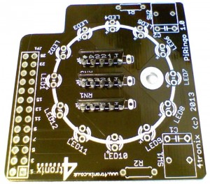
- Note that an unused hole is left at the other end (this hole is to allow different components to be used if 5-pin networks become unavailable for any reason)
- Then add the 2 switches, one either side in positions SW1 and SW2. It doesn’t matter which way round these are placed
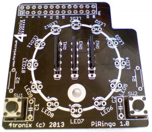
- If you are concerned about switch bounce you can add the two 100nF capacitors, C1 and C2. As they are included with the kit and not difficult to add, then we recommend that they are added. it doesn’t matter which way round they are fitted
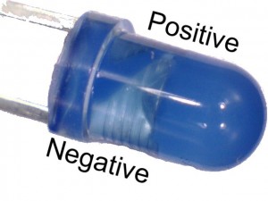
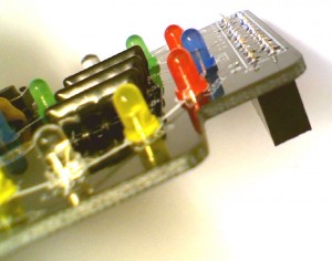
- Then add the LEDs. These are all the same way round with the long lead next to the ‘+’ on the PCB. The LEDs will not work if they are connected the wrong way round, but no damage will occur. You can also tell the negative lead by looking inside the LED itself. The lead with the large triangular plate is the negative lead.

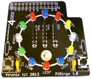
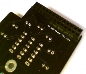
- Finally add the GPIO connector. This must be added to the opposite side of the board!


Using the PiRingo
- Download example Python codes from our GitHub
- You can also view the PCB design schematic at the same location
- Download and install the Scratch GPIO v4 from @cymplecy
- Current example Python programs are:
- allon.py – switches all LEDs on
- alloff.py – switches all LEDs off
- flashdemo.py – goes through a sequence of flashing and chasing patterns. These are all coded as separate functions, so you can easily change to any sequence you require
- swing.py – moves a single LED under command of the two switches. See who can press the switches faster
- swing2.py – creates a range of LEDs for the fastest switch presser – when the bar reaches the other side, the winner is declared with flashing lights!
- Current example Scratch GPIO programs are:
- Traffic lights simulation
Pin Definitions
The Pin numbers below refer to the physical pin numbers on the GPIO header. To use these pin numbers in Python, be sure to set the GPIO mode as “Board” as shown here:
GPIO.setmode(GPIO.BOARD).
All LEDs and switches are Active Low. So set an LED to 0 to turn it on, set to 1 to turn it off. Switches are 0 if pressed, 1 if not pressed
- LED1 – pin 7
- LED2 – pin 11
- LED3 – pin 12
- LED4 – pin 13
- LED5 – pin 15
- LED6 – pin 16
- LED7 – pin 18
- LED8 – pin 22
- LED9 – pin24
- LED10 – pin26
- LED11 – pin 8
- LED12 – pin 10
- Switch 1 – pin 19
- Switch2 – pin 21