Pizazz – Sample programs in Python and ScratchGPIO

Python Example Scripts

Please note that these programs are provided “as is” and without warranty purely for the purpose of demonstrating how you can write your own code for this robotic vehicle.

If you have our SD card with ready-installed demos, you will find these programs in home/pi/Pizazz/

If not then from a terminal window (eg. LXTerminal) type or cut&paste the following to install:

wget http://4tronix.co.uk/pizazz.sh -O pizazz.sh

bash pizazz.sh

  • motorTest.py  Tests the motors by moving Forwards, Reverse, SpinRight, SpinLeft, Pause in a loop. Press Ctrl-C to exit. This program will also light the LEDs to show the direction it is moving. Two LEDs at the front for Forwards, 2 LEDs at Left for Spin Left, etc
  • ledTest.py  Simply tests the LEDs by cycling LED1, then LED2, then LED3 then LED4 then back to LED1 again. Press Ctrl-C to stop
  • sonarTest.py  Prints the distance from the ultrasonic sensor to the nearest reflective obstacle. Repeats every second. Press Ctrlc-C to stop
  • standardLF.py  This is a standard Line Follower algorithm (thanks to Zachary Igielman). Place a black line (eg. electrical insulation tape) onto a reflective surface and the Pizazz will check if either sensor hits the line. If, say, the left sensor touches the line, then the Pizazz will spin left until the sensor is no longer on the line, then it will start moving again. You may need to adjust the separation of the sensors, and/or the speed of the robot to follow your specific line
  • fuzzyLF.py  This line follower is a bistable line follower. It is always (after it has found the line) either turning left or turning right. If it hits a line with the left sensor then it know it needs to turn left to find the line again, so it keeps moving left until the right sensor detects a line, then it starts moving right. This has the strange effect of the Pizazz wandering around close to the line, but not necessarily sitting directly over it. It does mean the that the speeds can be increased and it is easy to make the Pizazz go around a track twice as fast as with a standard line follower. You probably will need to move the line follower sensors much closer together than for the standard line follower program


ScratchGPIO Example Scripts

Please note that these programs are provided “as is” and without warranty purely for the purpose of demonstrating how you can write your own code for this robotic vehicle.

If you have our SD card with read-installed demos, you will find these scripts by doing a File / Open within Scratch and selecting the Pizazz folder

Many thanks to Simon Walters (@cymplecy) for all his excellent work on this

Programming the Pizazz – Which Pins do What

pz01

Pizazz – A Robot Vehicle for your Pi, Complete with Sensors and Optional WiFi

Allocation of GPIO Pins

The following list of pin numbers assumes that you have exactly followed the wiring instructions here

For ease of use with ScratchGPIO all pins are specified as the physical pins on the GPIO header. In brackets, we put the standard Broadcom use of these pins

  • Left Motor: 24 (CE0), 26 (CE1). To move forwards set 26 to High and 24 to Low. (NB it is better to use PWM to get some speed control)
  • Right Motor: 19 (MOSI), 21 (MISO). To move forwards set 19 to High and 21 to Low. (NB it is better to use PWM to get some speed control)
  • LED1: 22 (GPIO25). Set Low to turn On, set to High to turn Off
  • LED2: 18 (GPIO24). Set Low to turn On, set to High to turn Off
  • LED3: 11 (GPIO17). Set Low to turn On, set to High to turn Off
  • LED4: 07 (GPIO04). Set Low to turn On, set to High to turn Off
  • UltraSonic: 08 (TXD). Set to an Output to send a 10µs pulse, then set to an Input to measure the return pulse
  • Left Line Follower: 13. This will be Low (0) for White (reflective) surface, and High (1) for Black (non-reflective) surface
  • Right Line Follower: 12. This will be Low (0) for White (reflective) surface, and High (1) for Black (non-reflective) surface


Using Batteries for the Pizazz

  • Although all other parts of the Pizazz will operate purely from 5V supplied to the USB connector on your Pi, you will need to connect the battery pack to the MicRoCon and switch it on, before the motors will operate
  • You should only use good quality rechargeable batteries that can provide at least 1A continuously. We strongly recommend Energizer Extreme rechargeables of at least 2000mAh
  • the MicRoCon has a voltage regulator which will happily and safely power your Pi as long as the battery voltage remains above 6V or so
  • If the batteries are getting low, you should safely turn off the Pi, then remove and recharge the batteries
  • You can also power the Pi and the motors from separate power sources if required. Unsolder the solder jumper on the MicRoCon (near the regulator) labelled PWR, then you can power the Pi by plugging in a USB power bank or similar into the the USB socket on the Pi – NB. You will still need to connect batteries for the motors to operate


Using the Motors

  • Each motor is driven by 2 separate GPIO lines
  • To make the motor move, one of these lines needs to be High and the Other needs to be Low
  • If they are both the same (either both High, or both Low) then the motor will not turn
  • To move the Pizazz forwards in a straight line: Set 19 and 26 High, and set 21 and 24 Low
  • To move the Pizazz backwards in a straight line: Set 19 and 26 Low, and set 21 and 24 High
  • To Spin Left on the spot, make the Left Motor move backwards and the Right motor move forwards: Set 26 Low, 24 High and set 19 High, 21 Low


ScratchGPIO Examples

You will require ScratchGPIO version 5.1.26 or later, and see here for tutorial examples

PizaaaDocs


Pizazz Low Cost Robotic Vehicle for Raspberry Pi

pz01

Pizazz – A Robot Vehicle for your Pi, Complete with Sensors and Optional WiFi

Specification

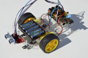
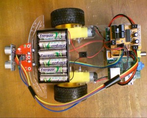
All true robots need some form of input sensors and outputs as well as motors, so we have created this ultra-cheap but full featured robot for your Raspberry Pi. Just look at some of the features:

  • Crystal Clear Pizazz chassis in 3mm acrylic plate
  • 2 pre-wired 48:1 geared motors, complete with noise suppression capacitors
  • No soldering, glueing or adhesive pads etc. All items simply plug or screw together
  • Fully assembled MicRoCon2 controller board – Optional Extended Header if required (select during purchase)
  • Low drop out voltage regulator to safely power your Pi and keep the power separate from the motors. No requirement for two separate battery packs
  • Custom designed 4tronix ultrasonic and LED PCB for easy fitting of the ultrasonic distance sensor and provide 4  individually controllable output LEDs
  • LEDs can be driven directly using Python or ScratchGPIO commands
  • InfraRed line sensors with adjustable positions
  • Wifi dongle (optional)
  • 6-cell battery holder
  • On-Off switch
  • All the wires, screws and mountings required
  • We also offer an optional SD card pre-loaded with ScratchGPIO, VNC, Python and example files in Pyhon and ScratchGPIO so you can get going straight-away
  • All you need to provide is the Raspberry Pi and the batteries

Links to Get you Started

Assembling Pizazz Robot for Raspberry Pi

Pizazz Assembly Instructions

NB. Click on any image to enlarge

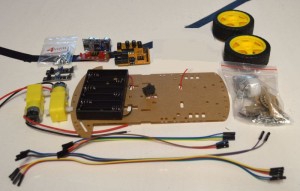
1. First check you have all the parts

pz03b

  • Main acrylic chassis plate with pre-wired battery pack and switch
  • Two motors with attached wires and noise suppression capacitors
  • 2 Wheels
  • Bag containing front caster wheel and mountings
  • 2 x line sensors
  • MicRoCon robotics controller board (assembled)
  • Ultrasonic and LED board (assembled)
  • 2 x 3-way 20cm jumper leads
  • 2 x 2-way 30cm jumper leads
  • 4-way 30cm jumper lead


2. Fit battery holder to chassis

step2

  • Remove the brown protective paper from the acrylic chassis plate
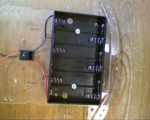
  • Push the switch into the hole until it clicks into place
  • Use 2 countersunk 12mm M3 screws and nuts to fit the battery holder. Ensure that the head of the screws lies flat inside the holder so that batteries fit in properly


3. Attach the motors

step3a

You require:

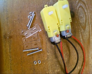
  • 4 x Motor mounts, after removing the brown protective paper
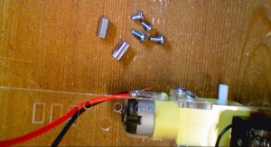
  • 4 x M3 30mm screws
  • 4 x M3 nuts
  • 2 x Motors

step3b

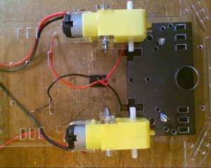
  • Mount the motors on tyhe bottom of the chassis plate (opposite side to battery holder)
  • For each motor, insert one motor mount through the slot in the top and the other sits in the slot on the edge of the chassis plate
  • Mount each motor with the wires on the outside as shown in the photo above
  • Push the 30mm screws in from the outside and attach the nuts on the insert
  • Make sure the motors a fitted flush to the chassis plate and do not move around


4. Fit the mounts for the Raspberry Pi

step4a

You will need:

  • 2 x 10mm hex spacers
  • 2 x M3 6mm pan head screws (to mount the spacer to the chassis plate)
  • 2 x M3 6mm countersunk screws (to mount the Pi to the spacers)

step4b

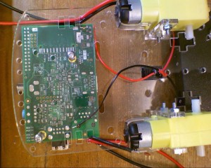
View from underneath showing the Pi mounted (don’t mount it now as you will need to remove for the next step)


5. Mount the Caster Wheel

step5a

You will need:

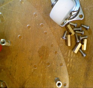
  • 4 x 10mm hex pillar (brass)
  • 8 x M3 8mm screws (pan head)

step5b

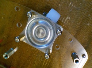
  • Screw the 4 pillars onto the bottom of the chassis plate using the holes shown above
  • Screw the wheel assembly into the pillars


6. Mount the Raspberry Pi and MicRoCon

step4b

  • Mount the Raspberry Pi to the pillars, using the countersunk M3 6mm screws
  • Push the wires from the switch/battery holder and the 2 motors through the holes in the chassis plate as shown

step6b

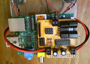
  • Push the MicRoCon onto the GPIO header of the Raspberry Pi. **Be very careful to ensure the pins are all correctly aligned **
  • Connect the battery wires to the front terminal block as shown: Red to Vin and Black to Gnd
  • Connect the left and right motors to the side terminal blocks. Note the colours of wires in the photo above:
    • Black is nearest the rear on the left side
    • Red is nearest the rear on the right side
  • If you wire these differently, then you will have to change all the example code for it to work correctly


7. Mount the ultrasonic Board

step7a

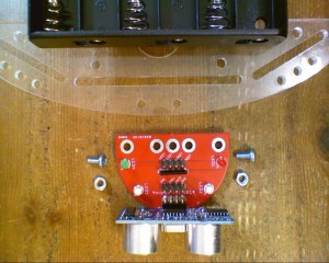
You will need:

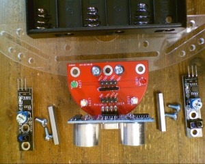
  • Ultrasonic and LED board (assembled). Note that you probably have Blue, Green, White LEDs and no Red LED. this is intentional
  • 2 x M3 6mm screws (pan head)
  • 2 x M3 nuts

step7b

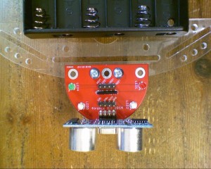
  • Screw the ultrasonic board into the top of the chassis plate, using the hole positions shown


8. Fit the Line Follower Sensors

step8a

You will need:

  • 2 x line follower sensors (with adjustable sensitivity)
  • 2 x 25mm hex pillars
  • 4 x M3 6mm screws (pan head)

step8b

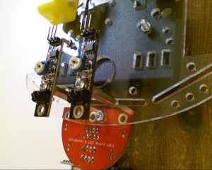
  • Use the holes nearer the middle of the line follower sensors
  • Arrange the sensors so the LEDs are pointing downwards
  • The terminal pins should be pointing towards the rear of the chassis


 9. Wire in the Ultrasonic Board

step9a

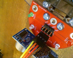
  • Use the 30cm 4-way cable
  • Connect:
    • Brown to Gnd
    • Red to Echo
    • Orange to Trig
    • Yellow to Vcc

step9b

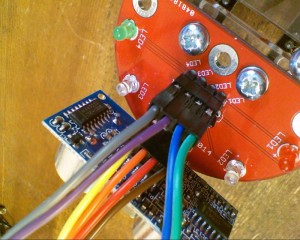
  • Use the 2 x 30cm 2-way cables
  • Connect:
    • Green to LED1
    • Blue to LED2
    • Violet to LED3
    • Grey to LED4

step9c

  • On the MicRoCon ultrasonic connector, connect:
    • Brown to Gnd
    • Red to Echo
    • Orange to Ping
    • Yellow to 5V
  • On the “Sig” pins next to the ultrasonic connector, connect:
    • Blue to 18 (physical GPIO pin 18)
    • Green to 22 (this is physical GPIO pin 22)
  • On the “Sig” pins on the 3V3 block of 4 x 3-way pins, connect:
    • Violet to 11 (physical pin 11)
    • Grey to 07 (physical pin 7)


Step 10. Wire in the Line Followers

step10a

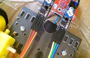
  • Left Line follower (shown from underneath, so it appears on the right in the photo), connect:
    • Yellow to Gnd
    • Green to V+
    • Blue to S (Signal)
  • Right Line follower, connect:
    • Brown to Gnd
    • Red to V+
    • Orange to S (Signal)

step10b

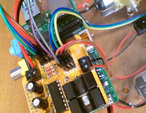
  • Right Line Follower sensor cable, connect to Pin 12 connections:
    • Brown to Gnd
    • Red to 3V3
    • Orange to Sig
  • Left Line Follower sensor cable, connect to Pin 13 connections:
    • Yellow to Gnd
    • Green to 3V3
    • Blue to Sig

11. Attach the Wheels – All Finished!

step11

NB. When pushing the wheels onto the motors, you MUST hold the motor and not the chassis, otherwise you are likely to break the motor mounts.

Now you can add the batteries, plug in your SD card and start programming