Pizazz Assembly Instructions
NB. Click on any image to enlarge
1. First check you have all the parts
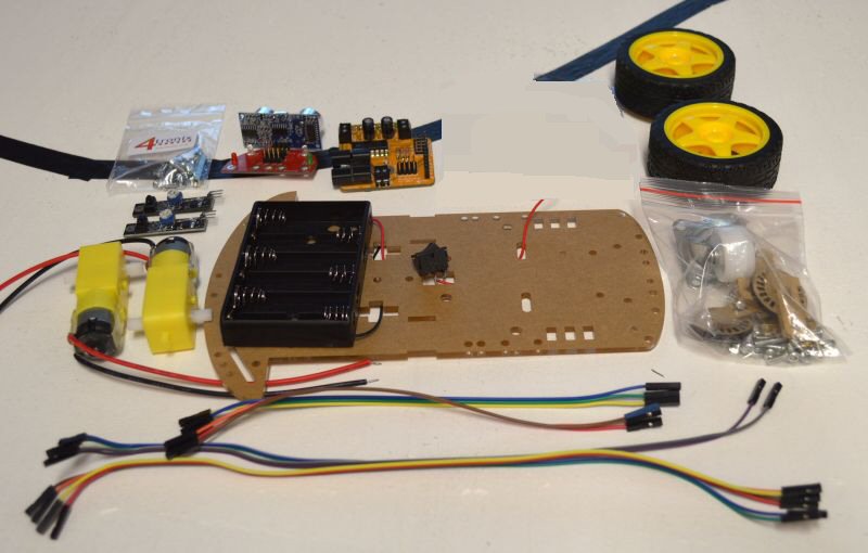
- Main acrylic chassis plate with pre-wired battery pack and switch
- Two motors with attached wires and noise suppression capacitors
- 2 Wheels
- Bag containing front caster wheel and mountings
- 2 x line sensors
- MicRoCon robotics controller board (assembled)
- Ultrasonic and LED board (assembled)
- 2 x 3-way 20cm jumper leads
- 2 x 2-way 30cm jumper leads
- 4-way 30cm jumper lead
2. Fit battery holder to chassis
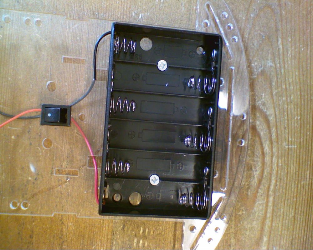
- Remove the brown protective paper from the acrylic chassis plate
- Push the switch into the hole until it clicks into place
- Use 2 countersunk 12mm M3 screws and nuts to fit the battery holder. Ensure that the head of the screws lies flat inside the holder so that batteries fit in properly
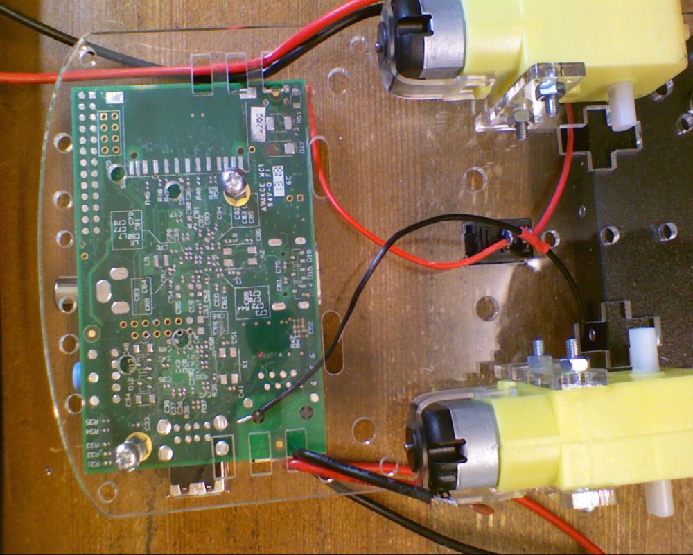
3. Attach the motors

You require:
- 4 x Motor mounts, after removing the brown protective paper
- 4 x M3 30mm screws
- 4 x M3 nuts
- 2 x Motors
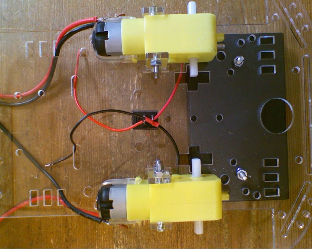
- Mount the motors on tyhe bottom of the chassis plate (opposite side to battery holder)
- For each motor, insert one motor mount through the slot in the top and the other sits in the slot on the edge of the chassis plate
- Mount each motor with the wires on the outside as shown in the photo above
- Push the 30mm screws in from the outside and attach the nuts on the insert
- Make sure the motors a fitted flush to the chassis plate and do not move around
4. Fit the mounts for the Raspberry Pi
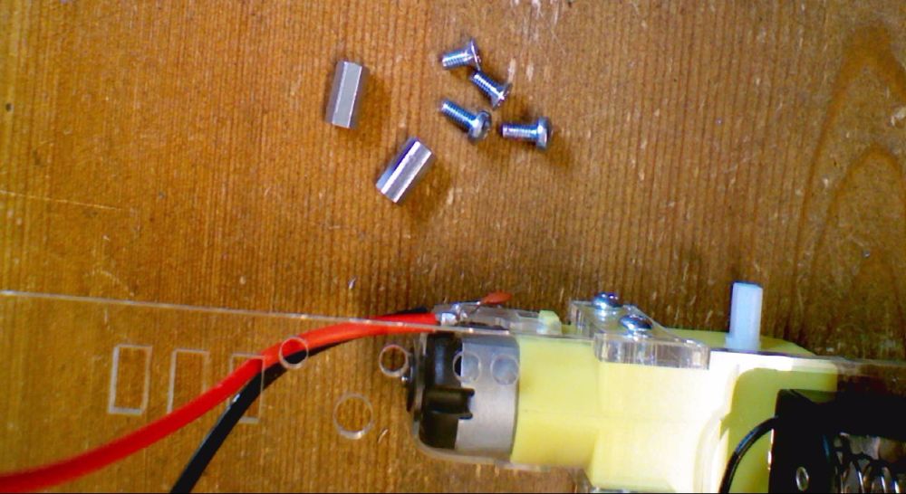
You will need:
- 2 x 10mm hex spacers
- 2 x M3 6mm pan head screws (to mount the spacer to the chassis plate)
- 2 x M3 6mm countersunk screws (to mount the Pi to the spacers)
View from underneath showing the Pi mounted (don’t mount it now as you will need to remove for the next step)
5. Mount the Caster Wheel
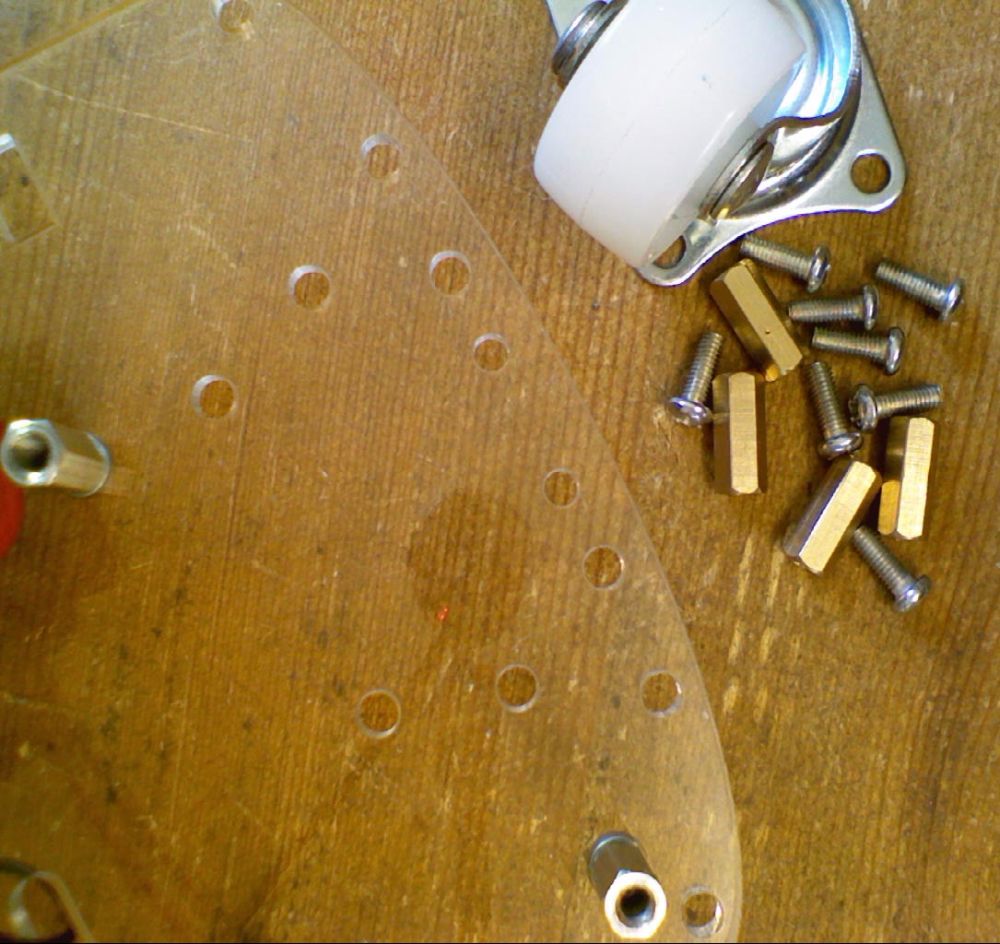
You will need:
- 4 x 10mm hex pillar (brass)
- 8 x M3 8mm screws (pan head)
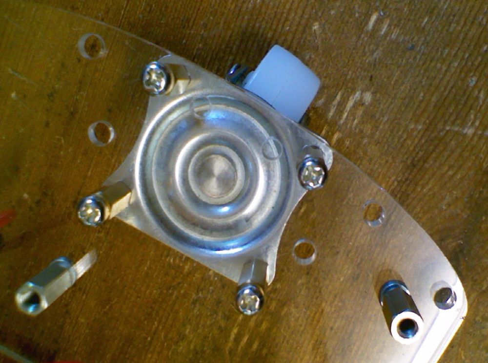
- Screw the 4 pillars onto the bottom of the chassis plate using the holes shown above
- Screw the wheel assembly into the pillars
6. Mount the Raspberry Pi and MicRoCon
- Mount the Raspberry Pi to the pillars, using the countersunk M3 6mm screws
- Push the wires from the switch/battery holder and the 2 motors through the holes in the chassis plate as shown
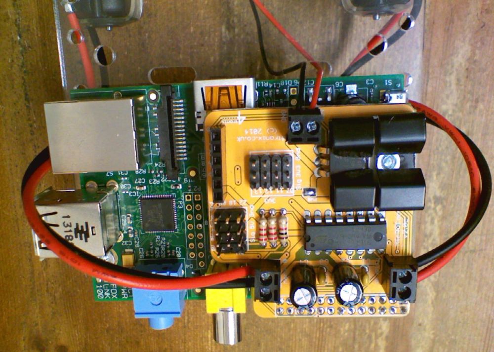
- Push the MicRoCon onto the GPIO header of the Raspberry Pi. **Be very careful to ensure the pins are all correctly aligned **
- Connect the battery wires to the front terminal block as shown: Red to Vin and Black to Gnd
- Connect the left and right motors to the side terminal blocks. Note the colours of wires in the photo above:
- Black is nearest the rear on the left side
- Red is nearest the rear on the right side
- If you wire these differently, then you will have to change all the example code for it to work correctly
7. Mount the ultrasonic Board
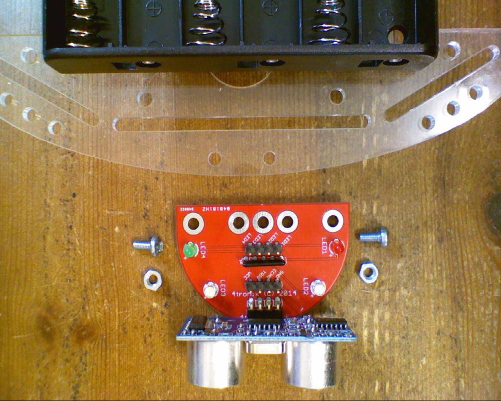
You will need:
- Ultrasonic and LED board (assembled). Note that you probably have Blue, Green, White LEDs and no Red LED. this is intentional
- 2 x M3 6mm screws (pan head)
- 2 x M3 nuts
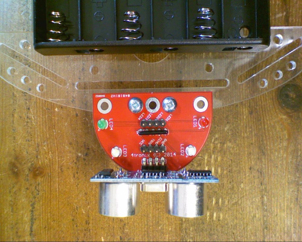
- Screw the ultrasonic board into the top of the chassis plate, using the hole positions shown
8. Fit the Line Follower Sensors

You will need:
- 2 x line follower sensors (with adjustable sensitivity)
- 2 x 25mm hex pillars
- 4 x M3 6mm screws (pan head)

- Use the holes nearer the middle of the line follower sensors
- Arrange the sensors so the LEDs are pointing downwards
- The terminal pins should be pointing towards the rear of the chassis
9. Wire in the Ultrasonic Board
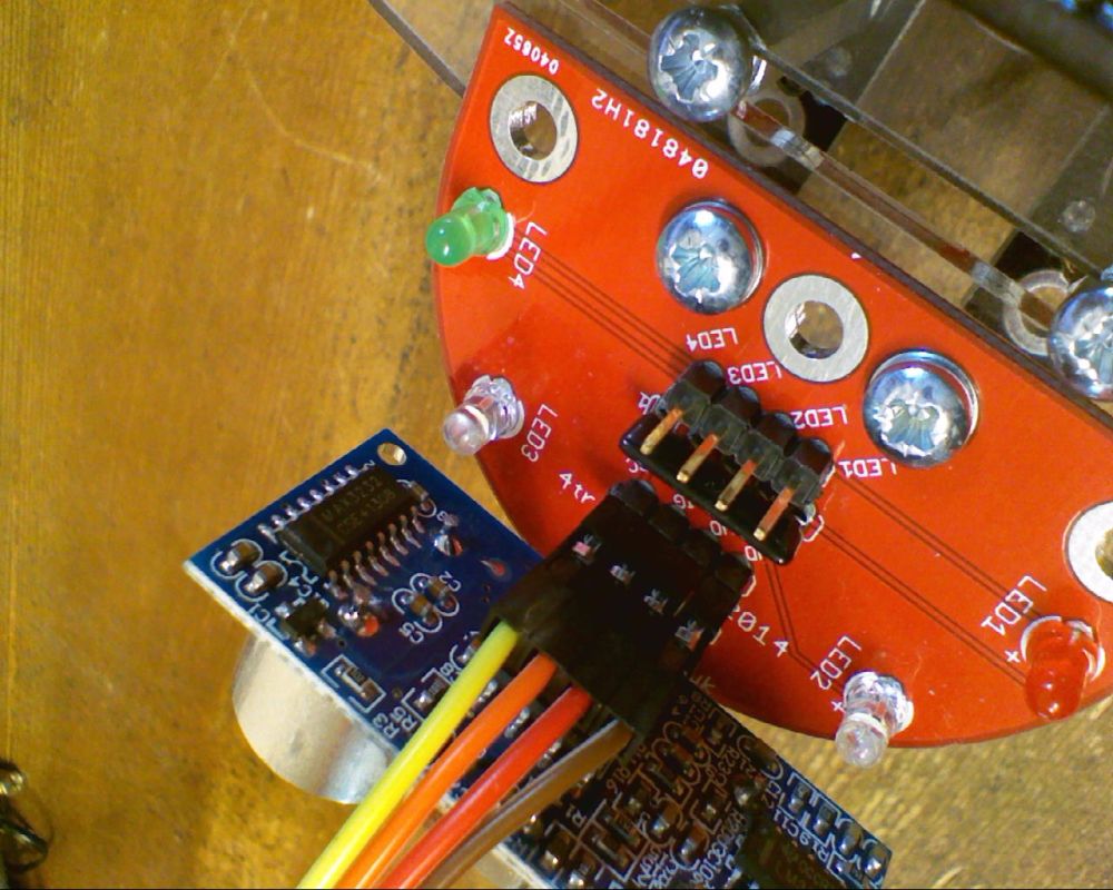
- Use the 30cm 4-way cable
- Connect:
- Brown to Gnd
- Red to Echo
- Orange to Trig
- Yellow to Vcc

- Use the 2 x 30cm 2-way cables
- Connect:
- Green to LED1
- Blue to LED2
- Violet to LED3
- Grey to LED4

- On the MicRoCon ultrasonic connector, connect:
- Brown to Gnd
- Red to Echo
- Orange to Ping
- Yellow to 5V
- On the “Sig” pins next to the ultrasonic connector, connect:
- Blue to 18 (physical GPIO pin 18)
- Green to 22 (this is physical GPIO pin 22)
- On the “Sig” pins on the 3V3 block of 4 x 3-way pins, connect:
- Violet to 11 (physical pin 11)
- Grey to 07 (physical pin 7)
Step 10. Wire in the Line Followers

- Left Line follower (shown from underneath, so it appears on the right in the photo), connect:
- Yellow to Gnd
- Green to V+
- Blue to S (Signal)
- Right Line follower, connect:
- Brown to Gnd
- Red to V+
- Orange to S (Signal)

- Right Line Follower sensor cable, connect to Pin 12 connections:
- Brown to Gnd
- Red to 3V3
- Orange to Sig
- Left Line Follower sensor cable, connect to Pin 13 connections:
- Yellow to Gnd
- Green to 3V3
- Blue to Sig
11. Attach the Wheels – All Finished!

NB. When pushing the wheels onto the motors, you MUST hold the motor and not the chassis, otherwise you are likely to break the motor mounts.
Now you can add the batteries, plug in your SD card and start programming