Introducing Pirocon 2
The “Gold standard” robotics controller for the Pi just got better!

As of this week (October 14th 2014), we are shipping version 2.0 of the Pirocon controller board. This has many changes from the previous v1.x versions.
Quick summary of changes:
- No changes to pinout or functionality – all existing software will continue to operate without change
- Board shape fits all models of Raspberry Pi including Model B+
- All active components now surface mount
- Big 3A regulator for the 5V supply of both the Raspberry Pi and sensors/servos
- Fully CE certified and RoHS compliant
- More energy efficient – batteries last longer
- Improved 3.3V-5V level shifters
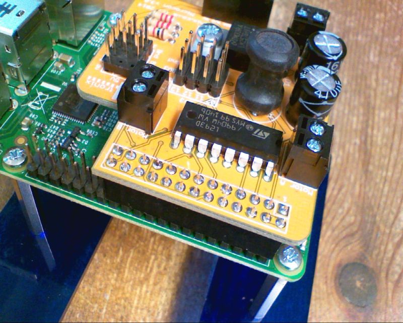
Pirocon2 Functional Layout

Clockwise from top left:
- Level shift selectors. Remove these jumpers if you want to use an input at 3.3V. Then you can connect directly the GPIO pin using the topmost pin freed by removing the jumper.
- Level shifted 3-pin block. A header with 8 sets of 3-pin connectors for 5V inputs or outputs. Note that Ground (0V) is furthest from the GPIO connector – this is opposite side to the Pirocon v1.x boards. From the top, each group of three is: Signal, 5V, Gnd
- The 2-pin screw terminal for connecting motor A
- A 4-pin terminal for directly connecting a 4-pin ultrasonic sensor – HC-SR04. This is converted on the Pirocon board to a single (selectable) pin into the GPIO
- The 2-pin screw terminal for connecting motor B
- Red indicator LED for 5V
- Orange indicator LED for 3.3V
- Selection jumper for GPIO pin to be used for ultrasonic. Default position is pin 8, but pin 23 can also be selected by moving the jumper to the left
- An 8-pin female header containing the SPI and voltage (5V, 3.3V, Gnd) signals
- This chip is the H-Bridge used to control the motors. It is an L293DD
- The 6-pin female header allows you to connect a 4tronix IP Display module or an Adafruit 16-channel PWM board (Adafruit model 815) for controlling multiple servos or LEDs. There are 2 of these headers (left and right) but they contain all the same signals so only one needs to be used, but is is more physically robust if the PWM board is plugged into both sockets.
- Selection jumper for motor voltage input. The voltage to drive the motors can be taken either directly from the DC jack input (which is used to generate the 5V for the Raspberry Pi), or from the 2-pin screw terminal on the lower edge of the Pirocon board. For most purposes, you will want this jumper to be on the right (nearest the edge of the board)
- The 2-pin screw terminal for an alternative motor power source. Note that this terminal does not power the 5V regulator so cannot be the only source of power
- A bank of 4 solder jumpers that connect the motor control pins to the selected GPIO pins. By default these are MISO, MOSI, CE0 and CE1. To change them, you should cut the tiny track between the two halves of the relevant jumper, then connect to the pin you want to use. This option is provided for flexibility, but most people will not need to change it
- These two jumpers permanently enable each motor driver. From a purest point of view, it is better to use these enable pins to provide the PWM signal to each motor and only use the motor control pins to determine the direction. However, in most circumstances it makes very little difference, so all the library software assumes 4-wire control and not 6-wire control. Leaving these jumpers in place ensures each motor is always enabled.
- Input DC jack for the regulator (and generally also for the motors). This is a 2.1mm pin jack, with centre positive. The voltage should be between 7V and 12V DC. Lower than 7V and the regulation may not be sufficient. Above 12V then the regulator may begin to overheat
- The left side connect for Adafruit’s PWM board – see item 11
- I2C and Serial (Rx, Tx) breakout female header
- Bi-directional level shifter chip. This converts the 5V signals to/from the 8×3 male header block into 3.3V signals for the Raspberry Pi
Software Support
- In ScratchGPIO, use the addon name “PiroconB”. Download from here
- For Python, use the standard Initio/Pirocon library available here. Although designed specifically for the Initio robot chassis, it will work unchanged for most robots with 2 drive motors
Errata
- Pins 15 & 16 (Broadcom GPIOs 22 and 23) are swapped from what is shown on the silk screen
- Pin 11 is shown as GPIO 07 on the jumper bank, instead of GPIO 17