Purchase >HERE<
Overview
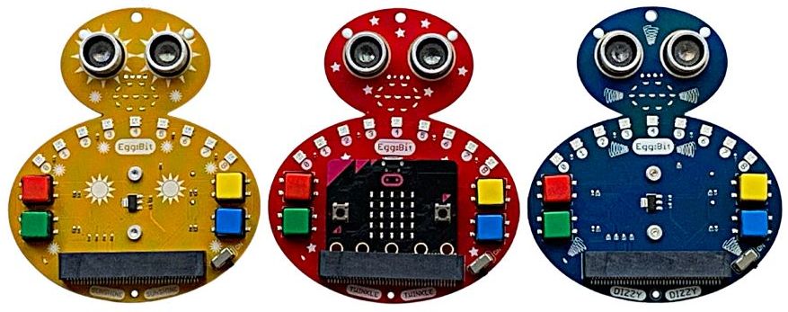
EggBit is a new wearable product for the popular Microbit. It comes with built-in RGB lights, buttons, animatable LED mouth and ultrasonic distance sensor. It also incoporates a battery pack, on/off switch, indicator LED and power circuitry.
EggBit is available in 3 functionally identical flavours: Sunshine, Twinkle and Dizzy
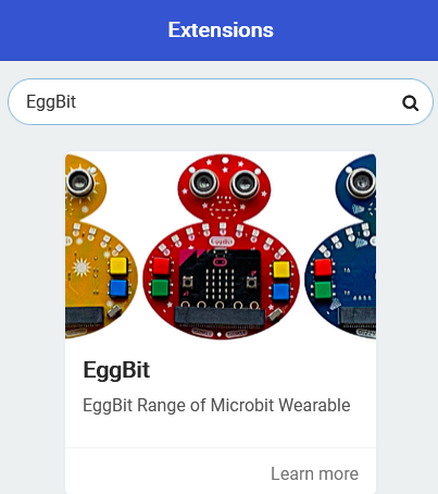
Coding them in Makecode is simpe. There is a Makecode extension written especially for them. Seacrh for EggBit in the EXtension search box.
Programming with Makecode
First you should load the EggBit extension to Makecode. Go to the Advanced section and select Extensions. Then in the search box, search for EggBit and then press Enter.
Then you can explore the various options. Within the EggBit extension are three categories: Input/Output, FireLeds and More
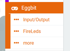
Input/Output section contains blocks to work with the buttons, the animatable mouth and the iultrasonic distance sensor.
FireLeds section contains the basic functions for driving the nine FireLeds, including use as a Larson scanner and a bar graph,
More section contains the advanced FireLed functions. Generally these will not be required.
Buttons
The four buttons can be coded in different ways. At any time in your code you can check the state of the button: whether it is pressed or not pressed. Alternatively, you can select a block that is only activated when the specified button is pressed or released (event-driven programming).
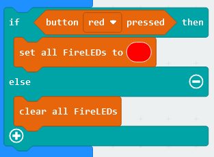
The following shows the method of checking the state of a button. This block is a “Boolean” value which can give the result True or False. It returns True if the button is currently pressed, otherwise it returns False. So it can be used directly in an if/then/else block as shown below. This example sets all the FireLeds to Red if the red button is pressed, otherwise it switches them off.
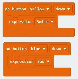
Using the event-driven model is equally simple. Select the button you want and whether you want to activate the block when the button is pressed, or when it is realeased. Then within the block you can run any code. The following two blocks set the mouth to Smile when the Yellow button is pressed and set it to Sad when the Blue button is pressed.
Mouth
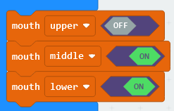
The animatable mouth has three separately controllable sections: Upper, Middle and Lower. You can control these sections individually if you like, or you can use the predefined expressions. As there are three sections and each can be either On or Off, there are eight possible configurations of the mouth.
For instance, to make an open, happy smile you would light the middle and lower sections, leaving the upper section off. You can do this by setting each part individually, like this:
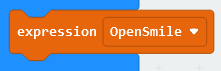
Or you could use the predefined expression, OpenSmile:
Ultrasonic Distance Sensor
This is a standard HC-SR04 type sensor that is specified to work from a few centimeters to a couple of metres. Note that as the beam angle is large, the further away the obstacle is, the larger it needs to be to provide sufficient reflection. This is normal behaviour.
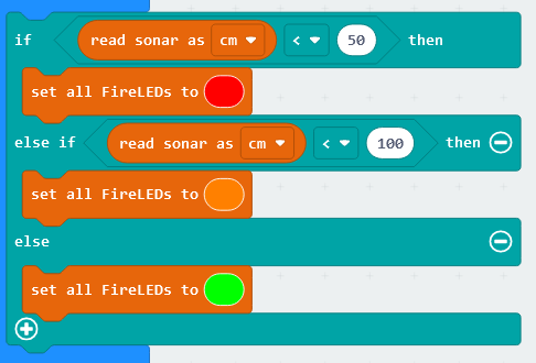
There is only one block for the ultrasonic sensor, which returns the distance to the nearest reflective object. You can select whether to get the answer in centimetres, inches or microseconds. In the following example, we set the FireLeds to Red if the object is less than 50cm away, Orange if less than 1m away, otherwise we set it to Green.
FireLeds
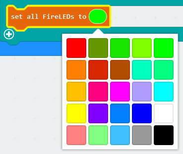
The EggBit has nine FireLeds, which are individually addressable RGB LEDs. You may have previously known them as neopixels. Each FireLed can be set to any of 16 million different colours, because the brightness of Red, Green and Blue components can each be set using 8 bit data (256 values each). To simplify setting the colours, we have produced a palette of 25 basic colours
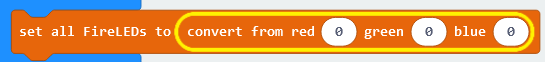
However, you can set the colour directly using the “convert from red, green, blue” block in the More category. Simply drop the convert block on top of the colour:
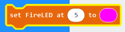
As well as setting all FireLeds to a specific colour, you can switch them all off using the “Clear all FireLeds” block, or set just a single FireLed to a specific colour using the “set FireLed at” block. The nine FireLeds on EggBit are clearly labelled with their number, from 0 to 8. This example sets FireLed 5 to Pink
Larson Scanner
You can set the Larson Scanner going by specifying the colour to use and the delay between display updates. The shorter the delay, the faster the scanner goes. Typically we set the colour as Red and the speed as 100 or 200ms

Use the “stop scanner” block to disable the scanner.
Bar Graph
The nine FireLeds can be configured as a bar graph, with the leftmost FireLed (0) being a low value and the rightmost (8) being a high value.
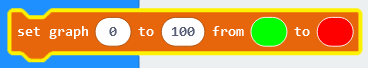
First, you must set up the parameters for the bar graph to work with. The system needs to know the colours to use for start and end and the value assoicated with the lowest LED and the highest LED. Use the “set graph” block to do this. The example below sets the range of values to be shown as 0 to 100 and the colours from Green to Red. The system will slowly change the colours so that the overall change starts at Green and ends at Red – in between there will be various shades of colour.
Now you can draw a bargraph by providing it with a number. The number doesn’t have to be in the range given, but anything higher than 100 (in the example above) woiuld be treated as 100, and anything lower than 0 would be treated as 0. The example below uses the value from the ultrasonic distance sensor to set the bargraph:
