Robo:Bit Mk2 Robotics Controller and Buggy for Micro:Bit

Looking for Robobit Mk3 ? Then Visit this Page
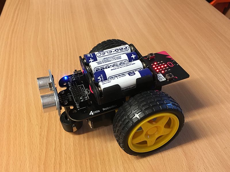
Robo:Bit Mk2 is a general purpose robotics controller for the BBC Micro:Bit, that also converts easily into a self-contained little buggy.
Purchase Robo:Bit here
Purchase the Robo:Bit Buggy here
Overview
The Robo:Bit controller has the following features
- Ready assembled (NB. headers for the underside are not fitted unless the complete buggy is purchased, but they are included in case you want to add these)
- Edge connector for easy attachment of your BBC Micro:Bit
- Dual motor driver with full control of each motor for both direction and speed (uses DRV8833)
- 3.3V Regulator to power the BBC Micro:Bit
- Power On/Off switch with LED indicator
- Mounting holes for either 3-cell or 4-cell AA battery holder
- Front interface for ultrasonic distance sensor (simply push-fit an HC-SR04, or solder for added security) [NB. You can also plug the McRoboFace into here directly and it will work as required!]
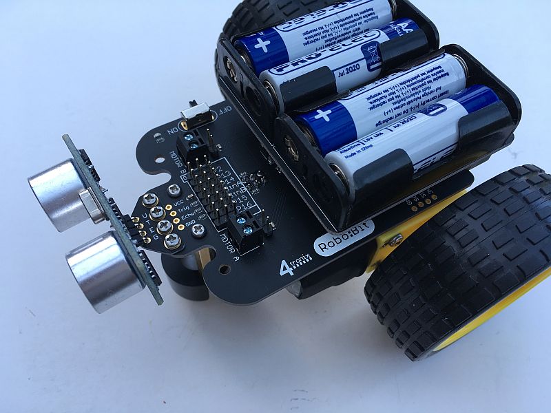
- 7 of the Micro:Bit pins are broken out to a header with GVS connections (Ground, Volts, Signal) for ease of connecting external devices and sensors
- I2C signals broken out in case you want to add more complex peripherals
Warning: The line follower sensors share the same pins as the buttons. Depending what language you are using, when the Micro:Bit is started or reset it will check the 2 buttons and start pairing if they are both pressed. With the Robobit, this translates to both line follower sensors getting reflections. You can stop it happening by lifting it off the surface before switching on, or of course disconnecting one or both of the sensors
Software & Programming
Robo:Bit uses the same connections for the motors as Bit:Bot, so most of the software will continue to work.
{{OLD INFO: In particular, the BitBot package for Microsoft PXT works fine (but you cannot use the sonar or neopixel blocks from this package as they use the wrong pins for RoboBit). To use this package, load up microsoft PXT for Micro:Bit from here, then go to Advanced or Tools and select Add package. Then search for “BitBot”.}}
Please use the currently Beta Robobit package. for Microsoft Makecode (aka PXT). Select Advanced, then “Add Package”. Into the search bar, put this URL: https://github.com/4tronix/Robobit and the Package will show as an Orange Taxi icon on the left.
The Pins are used as follows:
- Left Motor: Pin 0 (PWM) and Pin 8 (Direction)
- Right Motor: Pin 1 (PWM) and Pin 12 (Direction)
- Ultrasonic detector: Pin 13 (alternatively neopixel output pin)
- Left line sensor: Pin 11 (bottom 3×2 header)
- Right Line sensor: Pin 5 (bottom 3×2 header)
For each motor there is a 2-pin screw terminal and a 2-pin male header. If fitted, there is also a 2-pin JST header underneath the board (used in the buggy). All three connectors for each motor are connected together.
Some sample PXT programs. Click on them to download the compressed HEX files. You can install them into your Makecode environment by selecting Projects and “Import File” and browsing to the HEX file on your PC
Motor Test
Simply moves forward and backwards to check the motors are connected OK

Sonar test with the Ultrasonic
Simply displays the distance measurement on the MicroBit

FollowMe Sonar Test
The Robot will move to within 15-20cms of an obstacle and then move forwards or backwards to stay within this range

Control your Robobit Buggy from another Microbit
The same code can be loaded into each microbit. The one on the buggy will receive the commands from the second one – in your hand. To load this code, copy the compressed HEX file from here onto your PC, and uncompress it. Then, from Makecode, select Project and browse to find where you put the HEX file. Install this onto both the controller and the buggy. Here is the complete code visually:

Assembling the Robo:Bit Buggy
STOP: Before continuing, please check which version of RoboBit you have as the assembly instructions differ. The version number is written on the underside of the PCB as v1.0 or v1.1 or v2.0
Note that this buggy can be purchased in modular form. You can use your own motors and wheels if you already have them – the little yellow motors are pretty ubiquitous, so many schools and hobbyists will already have them. This guide to assembly assumes you have purchased the complete kit, including the ready-soldered wires on the motors – if not you would have to connect the wires to the motors and use the screw terminals on the top of the board.
Click on the image below for a quick assembly GIF

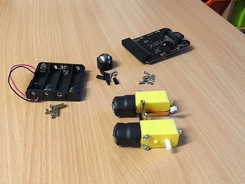
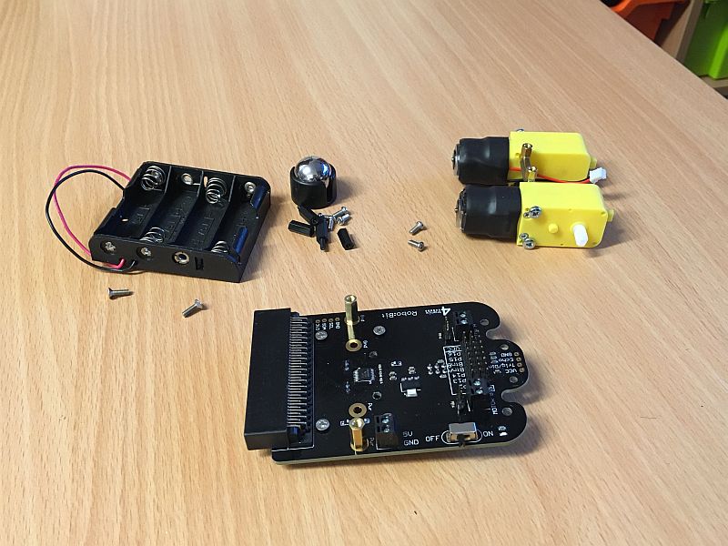
Step 1. Check you have all the Parts
NB. These are different for each Version. Check the PCB version (written on the underside of the PCB) before continuing
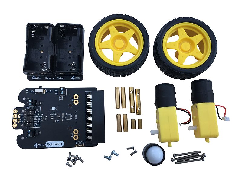
Version 2.0
- Robo:Bit v2.0
- Battery Holder with no wires, mounted on a PCB
- Yellow gear motors x 2 with JST connectors
- 1 caster (plastic ball plus plastic housing)
- 25mm brass female-female pillars x 2
- 11mm brass female-female pillars x 2
- 20mm brass female-female pillar (M2.5) x 2
- 30mm brass female-female pillar (M3) with holes x 2
- 6mm M3 screws x 2
- 30mm M2.5 screws x 4
- 6mm M2.5 screws (pan head) x 6
- 8mm M2.5 screws (CSK) x 2

Version 1.1
- Robo:Bit v1.1
- Battery Holder
- Yellow gear motors x 2
- 1 caster (plastic ball plus plastic housing)
- 10mm black nylon male-female pillars x 2
- 15mm black nylon female-female pillars x 2
- 20mm brass female-female pillar (M2.5) x 2
- 30mm brass female-female pillar (M3) with fitted attachments x 2
- 11mm brass female-female pillars x 2
- 25mm M3 screws x 4
- 6mm M2.5 screws (pan head) x 6
- 8mm M2.5 screws (CSK) x 2
- 4-cell AA battery holder
Version 1.0
- Robo:Bit v1.0
- Battery Holder
- Yellow gear motors x 2
- 1 caster (metal ball plus plastic housing)
- 10mm black nylon male-female pillars x 2
- 15mm black nylon female-female pillars x 2
- 25mm black nylon female-female pillar (M3)
- 25mm brass female-female pillar (M3) with fitted attachments
- 11mm brass female-female pillars x 2
- 25mm M3 screws x 4
- 6mm M2.5 screws (pan head) x 8 (or x10 – see step 6)
- 8mm M2.5 screws (CSK) x 6 (or x4 – see step 6)
- M2.5 nuts x 4
- 4-cell AA battery holder
For v1.0 assembly, go to Step 2A
For v1.1 assembly, go to Step 2B
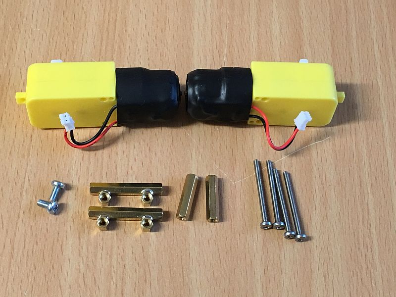
Step 2 (v2) Make the Motor Assembly v2
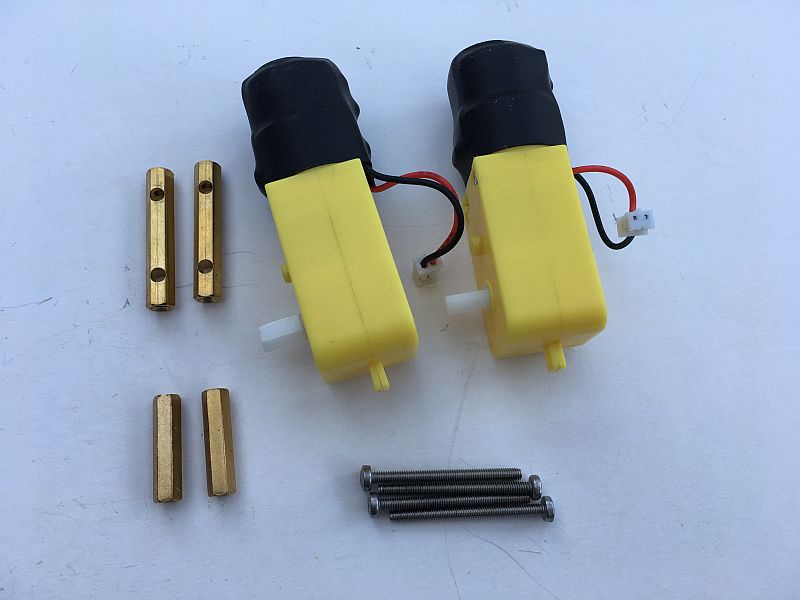
You will need the two 30mm brass pillars with holes, two 20mm brass pillars and 4 long (30mm) M2.5 screws

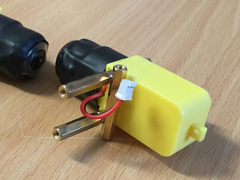
Push two of the screws through the holes in one of the motors and through the holes in the 30mm pillar as shown. Take care that the axle of the motor is on the outside and the pillar is on the inside. Also ensure that the motor wires do not get trapped under the pillar.
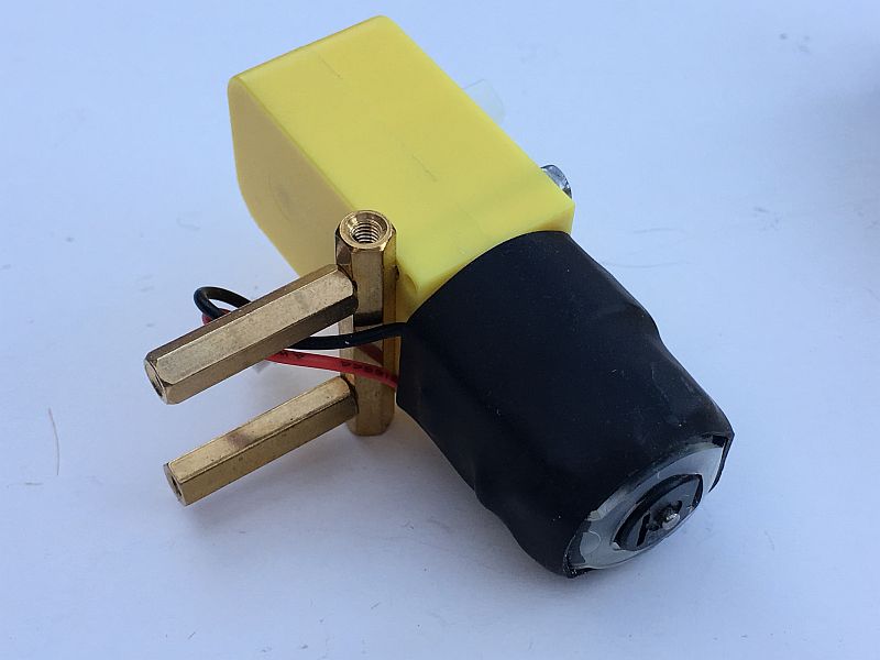
Screw the 20mm pillars on tightly as shown above.

Then fit the remaining 2 long screws through the second motor, ensuring the orientation is correct as shown above

Finally, screw the second motor firmly to the 20mm pillars. You have now completed the motor mount assembly. Now skip to Step 3
Step 2B (v1.1). Make the Motor Assembly v1.1
You will need the 2 brass bracket assemblies, 20mm female-female pillars (x2) and 30mm M2.5 screws (x4)

Push the 30mm screws through the motors as shown, with the screw threads protruding through the side with wires

Slide the bracket assemblies onto the ends of the 30mm screws as shown above. Ensure that:
1. The vertical 30mm pillar is away from where the wires exit the front of the motor
2. The wires go over the vertical pillars, not under them
3. The short spacers stick out on one side – this is the side that fits against the motor – do not try to fit them the other way around
Screw the two 20mm female-female brass pillars onto one motor as shown above

Finally, add the second motor and screw tightly together
Step 3. Prepare the Robo:Bit for Fitting
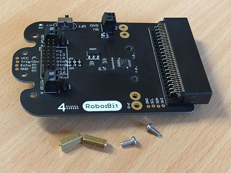
You will need the Robo:Bot circuit board, 6mm M2.5 screws (x2) and 11mm pillars (x2)

Fit the pillars in the positions shown above and screw tightly together
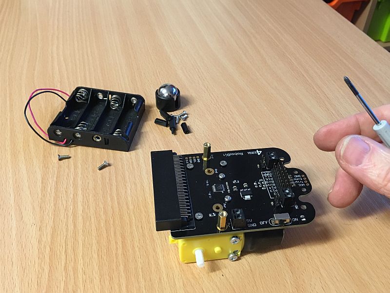
Step 4: Fit the Robo:Bit to the Motor Assembly

You will need the motor assembly from Step2, the Robo:Bit assembly from Step3 and M3 6mm screws (x2)
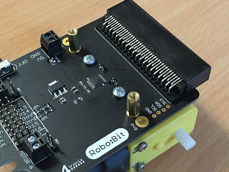
Pass the M3 6mm screws through the Robo:Bit board and into the top of the pillars in the brass bracket assemblies as shown above

Plug the two cables in making sure the left motor is plugged into the left socket and the right motor is plugged into the right socket

The photo above shows the gap between the motors and the Robo:Bit board
Now skip to Step 5
Step 2A. Make the Motor Assembly v1.0
Place the motors into position as shown above, with the axles facing outwards
Use 2 of the 25mm screws to fit the M3 black nylon 25mm female-female spacer to the bottom holes in the motor
Use the other 2 of the 25mm screws to fit the brass bracket assembly to the top holes, making sure that the connector parts point upwards as shown above
Step 3A. Prepare the Robo:Bit for Fitting

Fit 4 of the 8mm M2.5 CSK screws and the 4 nuts to the Robo:Bit as shown above. Pass each screw from the top of the board into a nut on the bottom. Tighten securely.
Using 2 of the 6mm M2.5 pan head screws, fit the 11mm brass pillars in place for the 4-cell battery holder – the outermost two holes – as shown above. Tighten securely
Step 4A: Fit the Robo:Bit to the Motor Assembly
Use 2 of the 6mm M2.5 pan-head screws to attach the Robo:Bit to the upwards-facing connectors on the brass bracket assembly as shown above. Tighten securely.
Push the JST plugs from the motors into the sockets underneath the Robo:Bit controller. The wires are short enough to stay tidy.
Step 5. Fit the Front Caster

For v1.0 and v1.1, Screw each 10mm black nylon male-female pillar into a 15mm making it into a 25mm female-female pillar.
For v2, use the 25mm brass female-female pillars
Use a 6mm M2.5 pan-head screw to fit each pillar to the front holes on the Robo:Bit
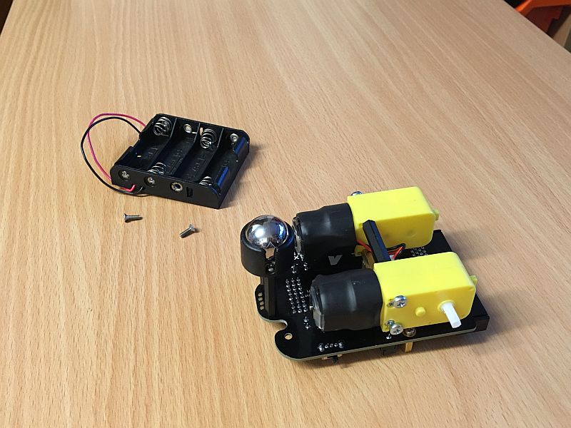
Then use two more 6mm M2.5 pan-head screws to fit the caster housing to the pillars (you will have to remove the metal ball while you do this)
Move to Step 6A for v1.0 and v1.1
Step 6 (v2): Fit the Battery Holder

You will need the battery holder assembly and the two 8mm countersunk screws
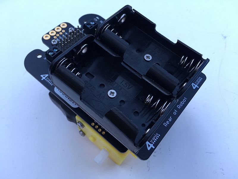
Screw the battery holder assembly tightly to the upright pillars, ensuring that the labelling is at the rear of the Robo:Bit as shown above. There is no need for wires as the battery power passes directly through the upright pillars.
Step 6A (v1.0 and v1.1): Fit the Battery Holder

Screw the wires into the power terminal. Red to 5V and Black to GND. Wrap the wires tidily out of the way under the battery holder

Use the remaining 2 of the 8mm M2.5 CSK (or 6mm pan head) screws to screw the battery holder to the brass mounting pillars. With some battery holders, the wide countersunk screws don’t fit, so swap them with the 2 smaller pan-head screws used to hold the mounting pillars for the front caster
Step 7. Finish off and Go!
 v1.0 or v1.1 Ultrasonic
Push on the wheels. Be careful to hold the motor as the wheels can be quite stiff to fit, especially the first time
Push in or bolt on the Ultrasonic Sensor (if you have one)
 v2 Ultrasonic
Push the BBC Micro:Bit into the edge connector (LED display and buttons upwards)
Program -> Switch On -> Go!
Fitting the Line Sensors
Step 8. Check you Have the Parts

- 30mm black nylon M3 pillars
- 6mm M3 screws x 4
- Line follower sensors x 2
- 10cm GVS cables x 2
Step 9. Fit the pillars to the Robo:Bit

Use 2 of the 6mm M3 screws to fit a 30mm black nylon pillar to each front corner of the Robo:Bit board
Step 10. Fit the Sensors

Push one of the GVS leads onto each line follower sensor. Make sure you use the colour coding: Brown for Ground (G), Red for volts (V+) and Orange for Signal (S)
Then use the remaining 2 of the 6mm M3 screws to to fit the line sensors to the bottom of each pillar. Use the hole near the centre of the sensor, not the one at the front. The wires should be at the back, as shown above
Step 11. Plug the GVS leads into the Connector

Pass the wires around the motor supports and then into the 3×2 male header underneath the Robo:Bit board. Make sure brown goes to Ground (GND), Red to power (3V) and Orange to Signal (SIG)
Also make sure you connect the left one to the left set of pins, and the right one to the right set of pins. It is VERY confusing when writing programs with these reversed (trust me, I know this)
Step 12. Trim the Sensors
Each sensor has a little preset potentiometer (pot) which can be turned to define the position at which it detects a line.
Turn the pot until the red LED on the sensor _just_ turns off. It is then at its most sensitive.
When using 3V, these sensors are not as sensitive. With a little ingenuity (and a different cable) you can connect the power line to VCC (the bottom 3 pins on the 8×3 header on the top of the board). This will make the sensors more sensitive.