About 4tronix Initio

The Initio 4WD robot platform has been specially designed here in the UK to work easily with Arduino and Raspberry Pi controllers. Supporting products include motor driver boards, sensor shields, sensors, pan-tilt mechanisms and more. We also have a range of kits available for both Arduino and Raspberry Pi platforms
Outline Specification
- An extremely flexible and easy to use 4WD Robot platform designed by 4tronix especially for Raspberry Pi and Arduino
- Injection moulded from tough ABS
- Built-in powerful 170-size motors and high-quality gearboxes
- Arduino (UNO, Mega2560 or Leonardo) and Raspberry Pi mount directly onto the base-plate
- 6-cell battery box with switch, charging socket, wiring for motor driver and Arduino already in place
- Built-in speed encoders on each side with electronics already fitted
- Each wheel can be individually decoupled from the gearbox – run as 1WD, 2WD or 3WD if you want!
- Fixings for stepper motors (28BYJ-48 as found in our shop – not included) so you can replace the DC Motors with stepper motors for greater accuracy
- No soldering or gluing required – simply screw together and plug in the wires (of course you can add things we haven’t thought of and they may need soldering)
- The main chassis is delivered ready-built and all wires connected
- All you need to do is add in the control boards and screw on the top plate
- Mounting plates included for IR obstacle sensors and Line sensors
- Loads of extra mountings for additional boards included
Purchasing Initio
- Purchase Initio kits here
4tronix Initio Assembly
Online Guides:
- START HERE: Assembling the Initio Chassis
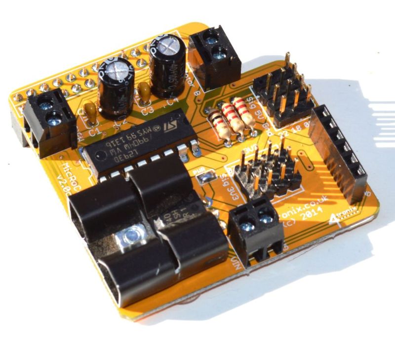
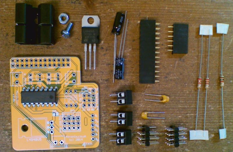
- Assembling Ultimate & Super Initio Kit with RoboHat
- Assembling Ultimate Initio Kit with Pirocon
Other Assembly Information
- ARDUINO: Assembling with an Arduino and L298N motor board
- Assembling with Raspberry Pi and L298N motor board
- STEPPER MOTORS: Modifying the Initio to use stepper motors instead of DC motors
- 4tronix SD card image: download
Downloadable PDF Guides:
TroubleShooting
Motors Not Turning
- For Raspberry Pi, ensure you are using correct software. Use the software in “robohat” folder if using RoboHat, or in “initio” folder if using Pirocon
- Batteries. You must use good quality rechargeable batteries, not alkaline. We strongly recommend Energizer Extreme 2300mAH
4tronix Initio Programming Examples
Arduino
Arduino examples are found in our Arduino support site
- initio_01 simply moves initio back and forwards and spins
- initio_02 uses PWM to control the speed and create smooth turns
- initio_03 shows how to use the speed sensors to move accurate distances
- EncoderTest01 tests the operation of both wheel sensors. Use the switches on the top of the gearbox to disengage the wheels from the gears, then turn the wheels by hand to see the results on the serial monitor
- initio_04 uses the obstacle sensors to avoid obstacles
- initio_05 adds a light-follower function using LDRs mounted on the Pan/Tilt (Connect one end of each LDR to 0V, the other ends to A0..A3)
- initio_06 uses the line sensors to follow a black line and stop when it reaches a cross-roads
- initio_07 uses the ultrasonic sensor mounted on the Pan/Tilt to avoid obstacles and travel in the direction of most space
ScratchGPIO
Raspberry Pi ScratchGPIO examples are found in our GitHub
- MotorTestB.sb Allows control of the motors using arrow keys (ScratchGPIO)
- PanTiltTest.sb Allows moving the pan/tilt assembly using arrow keys (ScratchGPIO)
- UltraSonicTest.sb Shows operation of the UltraSonic sensor (ScartchGPIO)
- TrackerTest.sb Uses the ultrasonic sensor on a Pan/Tilt assembly to follow (ScratchGPIO)
- Avoider.sb Uses IR obstacle sensors and motors to avoid objects (ScratchGPIO)
- InitioTest.sb Uses line sensors, obstacles sensors and motors (ScartchGPIO)
- Also see this post for using the wheel sensors with Raspberry Pi and the PiRoCon
Python
Raspberry Pi Python examples can be downloaded from an LXterminal session and connected to the internet, type in or copy and paste:.
wget https://4tronix.co.uk/robohat.sh -O robohat.shThen type in:
bash robohat.shYou will then have a number of python examples in the robohat folder to try. Run them with:
sudo python filename.py- motorTest2.py: use the arrow keys to move forwards and backwards, spin left or spin right. Space to stop. Use . and , to increase or decrease speed
- sonarTest.py: Prints the distance in centimetres from the ultrasonic sensor, once every second
- irTest.py: Prints the state of the IR line and obstacles sensors, every time the state changes.
- servoTest.py: use the arrow keys to pan and tilt
NB. If using the older Pirocon controller the replace robohat with initio throughout the above.
C
Yes, you can now program the Initio for Raspberry Pi directly in C. What’s more, it works seamlessly with both the Pirocon and the RoboHat control boards so your program can work on either without being changed
Visit this link to find out more about this which was written by Dr Raimund Kirner at the University of Hertfordshire


