
Initio Robot Platform with Stepper Motors
(Click on any image to enlarge)

The Initio robot was designed to be able to use stepper motors as an option instead of the DC motors. It is fairly easy to put the motors in, but slightly trickier for the control of them.
The following instructions are mainly photo based, with only a few comments…
Starting Position

Loosen the inner 2 screws on the inside of one Gearbox

Remove the 2 outer screws to release the gearbox


NB. It is not necessary to remove the DC motor, but I show it here for completeness
Carefully unclip the motor. This probably requires 2 people: 1 to pull the motor out and one to hold back the retaining clips

Unscrew the wheel sensor from the gearbox. Keep the screws as we’ll use them to attach one of the stepper motors.
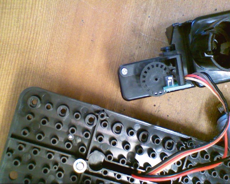

Slide the switch on top of the gearbox (one above each wheel) to the inside. this allows the wheel to rotate freely without turning the gears. It also means the stepper motor is mechanically disconnected from the DC motor so it is free to rotate.


Fit the stepper motor, ensuring that the shaft lines up with the retaining hole in the gearbox. Use the 2 screws that previously held the wheel sensor for one stepper motor. The other stepper motor will require 2 screws of the same size from the Initio pack of screws


Repeat for all 4 stepper motors and replace the gearboxes, bringing the cables up to the top of the chassis mounting plate


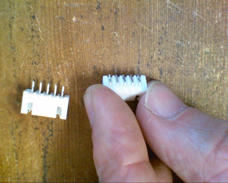
Prepare the ULN2003 boards for connecting 2 stepper motors to each board. If you purchased your stepper motors including boards, then you can remove the JST sockets from one board for each side of the Initio and use that as shown below. Otherwise you will need to purchase the correct JST sockets. We use a single controller board for both stepper motors on one side of the Initio, and solder the extra socket over the pins on the underside of the board as shown in the photos below.

Bend over the pins at 90 degrees (away from the side with the slots in). Then solder to the underside of the board


You can then screw the control boards into any available mounting pillars – one screw per board will keep it in place.

Next step: writing some code…