BitBot Programming in Python

BitBot and BitBot XL Programming in Python

Programming in Python

For text-based programming there is micro-python, and I prefer to use this offline using the Mu editor.  It provides a very neat and easy way of interfacing to the micro:bit without all the fuss of dragging and dropping.

Note on examples: We want to show people how the various features can be used. We don’t want to do the coding for you – that is the learning experience you should be taking away from using it. In the following examples, we will give you the tools to use all the features of Bit:Bot but it is up to you to combine them together in your code to make it do something useful. We do give a complete example of line-following – but it is a very basic algorithm and will get confused at T-junctions  and crossings; and it doesn’t use the FireLeds.

Download Python examples at the bottom of this page.

Some great tutorials/examples by Mark Atkinson here
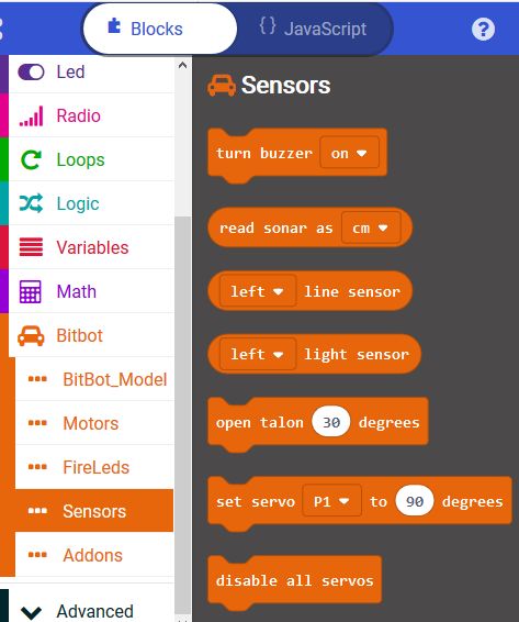
Motors

Each motor has two pins connected to it. If the first pin is High and the second is Low, then the motor will drive Forward. Conversely, if the first is Low and the Second is High then it will drive in Reverse.

For BitBot Classic: Left pins are P0, P8 and Right pins are P1, P12

For BitBot XL: Left pins are P16, P8 and Right pins are P14, P12

The simplest way to make the motors move Forward is to set the First pin to HIGH and the Second pin to LOW. eg for BitBot XL:

Move left motor Forwards:

pin16.write_digital(1)
pin8.write_digital(0)

Move left motor Reverse:

pin16.write_digital(0)
pin8.write_digital(1)

If we want to change the speed of a motor, so that it is not going at full speed all the time, we need to use PWM (Pulse Width Modulation). This is a means of changing the amount of power given to the motor by switching it on and off very fast. The percentage value of PWM determines the amount of each cycle that the output is ON. So a percentage of 100% is the same as being on all the time and thus the same as the examples above. A percentage of 50% would mean that the motor is only energised half the time, so it will go much slower. Note that the actual speed of the motor is not the same as the percentage of PWM – the motor won’t turn at all if the PWM value is too low and you will also get some stuttering at certain values. Nevertheless, being able to change the speed makes for a much better robot. For example, you can make a line follower that smoothly follows the line, rather than the normal shaking left and right.

To change the PWM value of a pin, we must use the analog_write commands. These can be set to a value between 0 (always off = 0%) to 1023 (always on = 100%), so 50% would be 511. Here are the commands to change the speed of the Right motor to approx 75% (value is 770) for the BitBot XL

Move right motor forwards at 75%

pin14.write_analog(770)
pin12.write_analog(0)

To move it in reverse, we simply apply the PWM value to the other pin instead and set the first pin to 0

Move right motor Reverse at 75%

pin14.write_analog(0)
pin12.write_analog(770)

FireLeds

The FireLeds smart RGB pixels are able to display any of 16 million colours by selecting a value of 0 to 255 for each of the Red, Green and Blue LEDs on each chip. The whole thing is controlled by a single pin on the BBC micro:bit (pin 13 for all models of Bit:Bot). It is simple to use the included neopixel libraries to control each FireLed individually.

The pixels are labelled on the Bit:Bot. From 0 to 5 on the left arm and from 6 to 11 on the right arm.

Set FireLed 2 to purple (red and blue)

from microbit import *
import neopixel
fireleds = neopixel.NeoPixel(pin13, 12)
fireleds[2] = (40, 0, 40)
fireleds.show( )

The first line is the standard import all from Microbit library.

The second line imports the neopixel library. We only need to do this once, at the very top of your Python program.

The third line creates a Python list with an element for each pixel. As shown, it specifies 12 pixels connected to pin 13.

The fourth line sets the pixel we have selected (number 2 in this case) to the colour which is set by three values in the brackets, each value can be from 0 to 255 and covers Red, Green and Blue. In our example we have set Red and Blue to 40.

The fifth line tells the neopixel library to copy all the data to the neopixels, from the Python list that we have been working with. It is only at this point that the LEDs change. In general, you would make all the changes you want and only at the end would you use a np.show( )

Line Follower Sensors

The pins used for line following are quite different for the BitBot Classic and the BitBot XL. BitBot Classic uses Pin11 (Left sensor) and Pin5 (Right sensor), which are the same pins as used for the Microbit’s two buttons. This can cause all sorts of issues.

The BitBot XL uses an I2C chip for these pins, with bit 0 of the resulting value being the Left sensor and bit 1 being the Right sensor.

The following two programs perform the same operation. They read the state of each line sensor and set the corresponding FireLed on the end of the stalks to either Red or Green.  The BitBot Classic first

from microbit import *
import neopixel
fireleds = neopixel.NeoPixel(pin13, 12)
while True:
    if(pin11.read_digital() == 0):
        fireleds[5]=(40,0,0)
    else:
        fireleds[5]=(0,40,0)
    if(pin5.read_digital() == 0):
        fireleds[11]=(40,0,0)
    else:
        fireleds[11]=(0,40,0)
    fireleds.show()
    sleep(200)

And now the equivalent program for the BitBot XL. You can see that we’ve defined a new function getLine( ) that reads the I2C device and returns the state of bit 0 (Left sensor) or bit 1 (Right sensor)

from microbit import *
import neopixel
I2CADDR = 0x1c # address of PCA9557
fireleds = neopixel.NeoPixel(pin13, 12)

def getLine(bit):
    mask = 1 << bit
    value = 0
    try:
        value = i2c.read(I2CADDR, 1)[0]
    except OSError:
        pass
    if (value & mask) > 0:
        return 1
    else:
        return 0

while True:
    if(getLine(0) == 0):
        fireleds[5]=(40,0,0)
    else:
        fireleds[5]=(0,40,0)
    if(getLine(1) == 0):
        fireleds[11]=(40,0,0)
    else:
        fireleds[11]=(0,40,0)
    fireleds.show()
    sleep(200)

The above programs are complete, with all the imports and defines required. This simple line following algorithm for the BitBot XL uses the getLine( ) function defined above as well as some simple motor functions which aren’t defined here

while True:
    lline = getLine(0)
    rline = getLine(1)
    if (lline == 1):
        spinLeft( )
    elif (rline == 1):
        spinRight( )
    else:
        forward(speed)

Light Sensors

These are analog sensors and will give a value of 0 to 1023, where 0 is fully dark and 1023 is maximum brightness

BitBot XL: On the BitBot XL these sensors are connected to Pin1 (Right) and Pin2 (Left). To get the current values of each sensor into variables rightVal and leftVal:

rightVal = pin1.read_analog()
leftVal = pin2.read_analog()

BitBot Classic: As there are only 3 analog pins available on the micro:bit (without affecting the LED displays) and we are using 2 of them to control the motors, we only have one left (Pin 2) to read the analog values from 2 line sensors. How can we do this? Well, the Bit:Bot has an analog switch that uses a digital output signal (pin 16) to determine whether the analog input we are reading is for the left sensor or the right sensor.

Therefore, to read the light sensors we need to set the selection output pin first, then read the analog data.

In Python, we can do it like this to read the values into 2 variables called leftVal and rightVal:

pin16.write_digital(0) # select left sensor
leftVal = pin2.read_analog()
pin16.write_digital(1) # select right sensor
rightVal = pin2.read_analog()

Buzzer

The buzzer is a very simply device that outputs a 2.4kHz sound when it is set to ON. It is NOT controlled by the tone signal that can be output by the micro:bit on Pin 0 so you don’t need to install any libraries to operate it.

It is connected to Pin14. Setting this to ON (1) will activate the buzzer and setting to OFF (0) will deactivate it.

In Python, a very simple and annoying beep, beep, beep sound can be made as follows:

while True:
    pin14.write_digital(1)
    sleep(400)
    pin14.write_digital(0)
    sleep(400)

Ultrasonic Distance Sensor

This optional HC-SR04 ultrasonic distance sensor addon can be used most easily in Microsoft PXT. In MicroPython we can use the utime module to measure time at microsecond level. Below we have a function called sonar() which returns the number of cm to the nearest object. Then we have a while loop that prints the distance every second:

from microbit import *
from utime import ticks_us, sleep_us

SONAR = pin15

def sonar( ):
    SONAR.write_digital(1) # Send 10us Ping pulse
    sleep_us(10)
    SONAR.write_digital(0)
    SONAR.set_pull(SONAR.NO_PULL)
    while SONAR.read_digital() == 0: # ensure Ping pulse has cleared
        pass
    start = ticks_us() # define starting time
    while SONAR.read_digital() == 1: # wait for Echo pulse to return
        pass
    end = ticks_us() # define ending time
    echo = end-start
    distance = int(0.01715 * echo) # Calculate cm distance
    return distance

while True:
    display.scroll(sonar())
    sleep(1000)

Programming BitBot XL

BitBot and BitBot XL Programming in Makecode

BitBot XL is the latest incarnation of the popular BitBot robot. It has the following features:

  • 2 micro-metal gear motors. Both fully controllable in software, for both speed (0 to 100%) and direction (forward or reverse)
  • Wheels with rubber tyres for maximum grip
  • Front ball caster
  • 12 FireLeds in 2 sets of 6 along the arms either side. Select any colour for any pixel, produce stunning lighting effects as your Bit:Bot XL moves around
  • 2 digital line following sensors with indicator LEDs. Code your own line-following robots and race them to see whose code produces the fastest lap time!
  • 2 analog light sensors (front left and front right) so your Bit:Bot XL can be programmed to follow a light source such as a torch, or you could code it to go and hide in the darkest place it can find
  • Buzzer, so you can make beeping sounds or music whenever you want
  • Powered from integrated 3xAA battery holder with on/off switch and blue indicator LED
  • Easily plug your BBC micro:bit in and out using the vertical edge connector
  • Expansion connections at the front for accessories. Currently available accessories: Ultrasonic, 5×5 FireLed matrix, BitFace and OLED
  • Two GVS connectors with 5V for servos (shared with light sensors)

Calibrating the Motors (v1.2 or later Only)

For version 1.2 of BitBot XL we have added code and hardware to help calibrate the motors on either side so that they match speeds better. Once the motors are calibrated, the calibration values are permanently remembered on the BitBot XL, so even using different Microbits and different programs, you will still get the matched motors. For this to work you must use the latest BitBot XL Makecode extension.

The calibration Makecode program can be downloaded from >here<. Load it into your Makecode editor and download to the Microbit on the BitBot XL v1.2 or later.

Process: The calibration program starts at speed 30 (displaying 3 on the Microbit LEDs). You then set the left or right speeds until it is driving straight. Then give the BitBot XL a good shake and it will change to speed 60 (displaying 6). Set this speed, shake again to change to speed 90 (displaying 9). Once this speed is set correctly, shake again and it will return to speed 30. You can then switch off and all the values are stored. If you run the program again, you will start from the un-calibrated values and must follow all the steps again.

  • Load the program into the Microbit and plug it into the BitBot XL
  • Switch on the BitBot XL. it will display 5 (indicating a v1.2 BitBot XL), then change to show 3 (meaning speed 30)
  • Press A or B buttons to affect the turning left or right, then press both A+B simultaneously and the Microbit will display the current calibration value, then move forward for 2 seconds at speed 30.
  • If it is still not moving straight, press the appropriate button one or more times to straighten it up, then press A+B again to test it
  • When you’re happy that it is moving straight, give the BitBot XL a shake and it will store the values for speed 30 and move onto Speed 60.
  • Repeat for speed 60 and speed 90

Programming in Makecode

Python Programming can be found >here<

Tip: Click on any image to enlarge

Load Makecode for the Microbit from makecode.microbit.org and create a New Project. Then select the Advanced tab and click on Extensions. You should see BitBot on the extensions home page. If not, enter bitbot in the search box and select the extension when it shows up.

Setting the BitBot Model

The BitBot Makecode extension is fully compatible with all models of BitBot, including BitBot XL. The extension will automatically select the correct  version to use when it runs (as long as the BitBot is switched on when the program starts)

There are blocks available, in the “BitBot Model” category, to force a specific model (Classic or XL) as well as giving the ability to check which version the software is running on. This allows you to write programs that will run unchanged on all models of BitBot.

Controlling the Motors

In the motors category, you can select blocks to go forward or reverse, or spin on the spot. Both types of block can optionally be run for a fixed time, then the robot will stop.

In addition you can stop BitBot with the stop block. This can be a fast stop with an electronic brake, or the robot can more slowly come to rest.

You can also drive each motor individually. This allows you, for example, to turn the left wheel slowly and the right wheel fast so that the BitBot curves smoothly to the left.

Small DC Motors as used in the BitBot and other small robots are never fully matched. To take account of this you can bias the motors to move in the opposite direction to their natural curve. For example, if the robot curves to the left when it should be travelling straight, add some right bias. Vice versa, if it curves to the right, then add some left bias.

Controlling the FireLeds

There are 12 FireLeds on the BitBot. Each of which can be individually controlled with 16 million different colours (not that you can distinguish that many).

By default, the FireLeds are updated as soon as you make any change to them. If you are doing more complicated changes, you may want to change to manual updating so that you make all the changes required, then update the FireLeds once at the end. This is more efficient and gives a tidier appearance to animations, but isn’t necessary for the majority of uses.

You can set all of the FireLeds in one go to the same colour, using the “set all LEDs” block. If you click on the Red blob on the end of the block it will allow you to select one of 25 different colours (you can select your own colours as well, see the advanced blocks)

You can also set individual FireLeds (numbered 0 to 11 on the BitBot’s arms) to specific colours and clear all the FireLeds (switch them off). Setting the FireLeds to Rainbow, sets them all to different colours starting at Red and ending at Purple.

Blocks are also available to shift all the FireLeds along one place (with the FireLed 0 being turned off) and to rotate them all by one place (with FireLed 0 becoming the same colour that FireLed 11 was previously)

Advanced FireLed Control

In the advanced block we can set the brightness of all the FireLeds. The default setting is 40, but it can go as high as 255 for maximum brightness. Do not look directly at the FireLeds if they are set to very bright, especially if they are set to White, as it can hurt the eyes.

If you set the update mode to Manual (instead of Automatic) then you must run the “show FireLed changes” block after you make a change, otherwise nothing will change on the FireLeds themselves.

The final 2 blocks return a number representing a colour that you can select from the colour chooser or by setting specific Red, Green and Blue values. This colour number can be put into a variable for testing against other values, or you can use it directly to set the colour of FireLeds

Sensors – Buzzer, Light Sensors, Line Sensors, Talon, Servos

The Buzzer can be On (continuous beep) or Off (silent). On the BitBot XL, this can also be used to play music (badly) as it is connected to Pin 0. Use the standard Music blocks in Makecode to do this – it isn’t supported directly in the BitBot extension.

The optional ultrasonic sensor is used to measure the distance to the nearest sound reflecting object. This may be anything in the area as the focus of the sound beam is not very tight, so it may pick up other objects than the one you want. This block returns a number that can be the number of cm, number of inches, or a raw microseconds figure.

Similarly the light sensors return a number from 0 (totally dark) to 1023 (maximum brightness).

The line follower sensors are slightly different. They return a value of either 0 (no black line) or 1 (black line).

The Servos (BitBot XL only) and the Talon (optional on all models) operate in the same way – as the Talon is just a servo really.

For the Talon you can select the angle of the servo from 0 to 80 (closed to open). On the servos (BitBot XL only) you can select an angle from 0 (fully clockwise) to 180 (fully anti-clockwise)

If you want to release the pin from being a servo (as the servo pins on the BitBot XL are shared with the light sensors), then you can disable the servos.

Starting with ScratchGPIO on Pi2Go Mk2

Pi2Go Mark 2 with ScratchGPIO

Simon Walters (Cymplecy) has worked on ScratchGPIO for many years and continues to add new products to the supported list. Pi2Go Mk2 is now also supported – here’s a brief introduction on how to get started.

Step 1: Install ScratchGPIO

Visit the ScratchGPIO install page here.

From a command line, first run the wget to download the installer

wget https://git.io/vMS6T -O isgh8.sh

Then run the installer:

sudo bash isgh8.sh

Step 2: Run ScratchGPIO8Plus

Make sure you choose the correct program to run here. Do NOT run ScratchGPIO8, nor Scratch2GPIO…

Step 3: Create an Addon Variable

You need to create a variable and set it to “Pi2Go2” (without the quotes)

Select the Variables tab (top left) and press “Make a variable”

Name the variable “AddOn”

Move the block “set AddOn…” to the programming area and enter Pi2Go2 as the variable name.

While you’re at it, grab a green flag block from the Control tab and lock the 2 blocks together

Click on the green flag and the AddOn variable in the stage will show up as Pi2Go2 as in the image above.

Step 4: Check the Sensors are available

Now, when you look into the Sensing tab, next to the bottom is a block showing “slider sensor value”. If you click on the slider you can see all the other sensors available, including those for the Pi2Go Mk2: battery, frontleftlight, frontrightright, etc. You can now use all these sensors in your program.

Step 5: Drive the Motors

Now you can create two more variables for the motors. MotorL and MotorR for the Left and Right motors respectively.

Setting these to values between 0 and 100 will drive the motors. Note that speeds below 30 or so may not be able to power the motors – it depends what batteries and what voltage is available.

The program below drives the left motor for 1 second at speed 60, then stops

Step 6: Further Programming

Now visit the ScratchGPIO page dedicated to Pi2Go Mk2 for further tips and information.