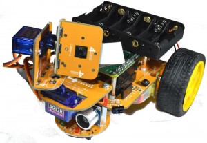
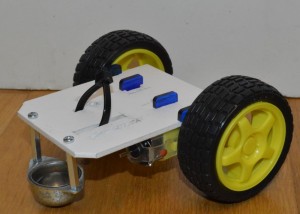
Pan & Tilt Kit for Pi2Go-Lite and Pi Camera

Pan & Tilt Kit for Pi2Go and Pi2Go-Lite

pt01a


You can download a PDF of this guide from here

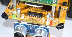
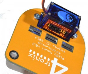
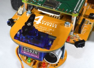
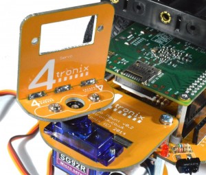
This system allows you to use the Pi Camera in 3 different ways with your Pi2Go or Pi2Go-Lite

  1. Fixed camera
  2. Camera with Pan control
  3. Camera with Pan and Tilt Control


All the parts are included in the kit for the complete Pan/Tilt assembly (except the Pi Camera which is an optional extra). You choose which system you want, and it is easy to change from one to another simply by undoing and replacing a few screws.


Step 1: Identify the Parts

pt04a

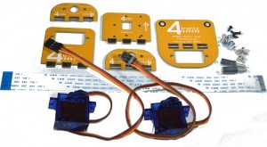
Included in the kit are the following parts:

  • 1 x Base mounting plate
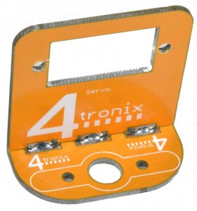
  • 1 x Servo mounting plate
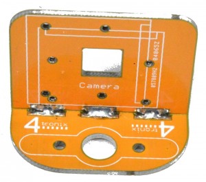
  • 1 x Camera mounting plate
  • 2 x Servo arm mounting plates
  • 2 x Tower Pro SG92R carbon fibre micro servos
  • 4 x M3 Self tapping 6mm screws (for attaching servo arms)
  • 4 x M2.5 screws 6mm (for mounting the servos)
  • 4 x M1.7 self-tapping screws 5mm (black, for mounting camera)
  • 2 x M3 male-female pillars 12mm
  • 1 x 200mm camera cable


Step 2: Solder the Camera Mount to a Servo Arm Plate

pt05a

  • Push the camera mount plate, with the camera markings on the inside as shown, into one of the servo arm plates
  • Tack solder in one place
  • Adjust the fitting until the camera mount is at right angles to the arm plate
  • Solder all the other places on both sides for maximum strength (in fact there is very little weight, so only a couple of points need soldering if you’re in a hurry!)


Step 3: Solder the Tilt Servo Mount to a Servo Arm Plate

pt07a

Make the tilt servo assembly in the same way as the camera mount assembly


Step 4: Attach the 12mm Pillars to the Pi2Go

pt08a

One at a time, remove the existing screws that hold on the front caster assembly on and replace them with the 12mm pillars.

Keep the screws for use in Step 6

Screw on firmly.


Step 5: Attach the Pan Servo to the Base Mounting Plate

pt09a

  • Push the servo through the hole in the base mounting plate  so the servo tabs are on the upper surface
  • Use 2 of the 6mm M2.5 screws to screw directly into the mounting holes of the servo from underneath


Step 6: Fit the Base Mounting to the Pi2Go

pt10a

Use the 2 screws you removed in step 4 to screw the base mounting plate

Attach  the straight servo arm using the small screw in the servo bag. Fit it so that it runs front to back as shown, when the servo is in its middle position


Step 7: Fit the Tilt Servo Mount Assembly to the Pan Servo

pt11a

Use 2 of the 6mm self-tapping screws provided. Do NOT use the 2 self-tapping screws in the servo bag as they are too long

The holes in the servo arm plate line up with the third hole out from the centre on each side of the servo arm.


Step 8: Fit the Tilt Servo into the Servo Mount

pt12a

This time, push the servo in from the back of the board and screw in using the last 2 of the 6mm M2.5 screws

Attach  the straight servo arm using the small screw in the servo bag. Fit it so that it runs top to bottom as shown, when the servo is in its middle position


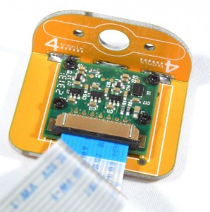
Step 9: Fit the Camera to the Camera Mounting Plate

pt13a

Use the 4 very small black self-tapping screws to mount the camera. DO NOT TIGHTEN the screws at all. Leave them loose or you will bend and damage the camera board

You can mount it in 2 positions, as shown on the silk screen. When used with both Pan and Tilt, we find it is best to mount it in the orientation shown above.

Fit the 200mm camera cable carefully into the camera connector


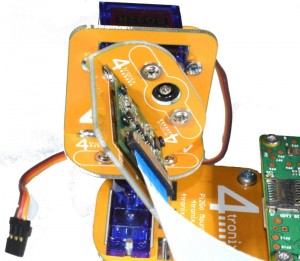
Step 10: Fit the Camera Assembly to the Tilt Servo Arm

pt14a

Use 2 of the 6mm self-tapping screws provided. Do NOT use the 2 self-tapping screws in the servo bag as they are too long

The holes in the servo arm plate line up with the third hole out from the centre on each side of the servo arm.


You have now completed the assembly of the Pan Tilt mechanism.

Fitting Wheel Encoder Sensors to Pi2Go-Lite

Wheel Encoders on Pi2Go-Lite

You can also download a PDF of this guide from here

These simple encoders provide 16 pulses per revolution of the main wheels and allow you to program your vehicle to:

  • Travel in straight lines, even if the motors naturally move at slightly different speeds
  • Travel a fixed distance
  • Turn a set angle

The Pi2Go-Lite is already able to take the sensors. Both the Python library and ScratchGPIO incorporates the sensors and allows you to easily write your own programs to use them as you wish.
The encoder/sensors are supplied as a kit and require some soldering to complete.


Fitting the Encoder Sensors

Step 1: Identify the parts

** NB. Please check you have the correct resistors in the pack BEFORE soldering. We think there may be a few wheel sensor packs with incorrect resistors, so please double check first as it is much easier to resolve the problem before soldering. Specifically the 10K resistors may be incorrect, check they have Brown, Black and Orange stripes

encoders01a

Note: Check which Pi2Go-Lite main PCB you have as the instructions are slightly different

  • v1.0: The selection jumpers are not included with v1.0 and a cut needs to be made on a solder jumper to enable wheel sensors
  • v1.1: The selection jumpers and header is included with the base kit, so not separately required for the wheel sensor kit
  • v1.2: The base kit includes a slide switch to select line follower or wheel sensors, so not required in the wheel sensor kit


  • 2 x encoder discs (if this pack was ordered at same time as the Pi2Go-Lite, the discs will already be fitted to the wheels)
  • 2 x IR reflectance sensors
  • 2 x resistors 10K (Brown, Black, Orange)
  • 2 x resistors 220R (Red, Red, Brown)
  • 3×2 male jumper block: Not required for v1.1 and above
  • 2 x 0.1″ jumpers: Not required for v1.1 and above


Step 2: Attach the Wheel Encoder Discs

step04a

I prefer to use 5 drops of superglue – one on each spoke of the wheel. Then drop the encoder disc into each wheel as shown, with the black/white markings uppermost. Leave to dry while you get on with the soldering.

If you prefer, you can also use double-sided adhesive pads

Ff the wheel sensor pack was ordered at same time as the Pi2Go-Lite, the discs will already be fitted to the wheels


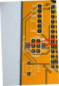
Step 3: Cut the Selector Tracks – v1.0 ONLY

step02a

** This step is only required for v1.0 PCBs

On the left of the Pi2Go-Lite is an empty position for the 3×2 male header block. To each side of that is a pre-linked solder jumper – click on the image above to enlarge and clarify. You need to cut these links carefully using a sharp craft knife. Be careful not to cut anything else!

When these links are cut and the jumper block added, then you can select whether to use line-follower sensors or wheel sensors. There are not sufficient available GPIO pins on the 26-0pin connector for both to be in operation at once.


Step 4: Add the IR Sensors

step03a

As when building the Pi2Go-Lite kit originally, you should cut the pins on the sensors, next to the flattened part on the legs. Then solder them on.

NB. The Blue LED for the left sensor is at the front, but the blue LED for the Right sensor is at the rear. Use the silk screen angles to identify.

Snip the plastic legs/fixings off the sensors, or these will impeded the mounting of the motors.


Step 5: Add the 10K Resistors (Brown, Black, Orange) – v1.0 Only ***

As shown in the image above, these need to be connected directly to the sensors on the top of the board.

Bend the legs on each resistor and cut off all but 4mm of the legs, then solder on carefully


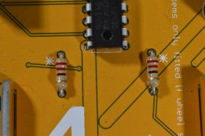
Step 6: Add the 220R Resistors (Red, Red, Brown)

ws_step6

These can be soldered into the middle of the board in positions marked with an asterisk.

** For v1.1 PCBs and above, also fit the 10K resistors (Brown, Black, Orange) to the positions next to the 220R resistors


Step 7: Add the Jumper Block – v1.0 Only

step05a

** v1.0 only Ensure you have cut the 2 tracks as described in step 3. It is really difficult to cut the tracks after the jumper block is fitted.

Now solder on the 3×2 male jumper block.

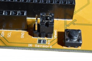
Important Info: The jumpers (or switch for v1.2 and above) can be placed in one of 2 positions:

  • Front: Use the line follower sensors
  • Rear: Use wheel sensors


The wheel sensors are now ready to go.


Programming PiRoCon in Python

Python

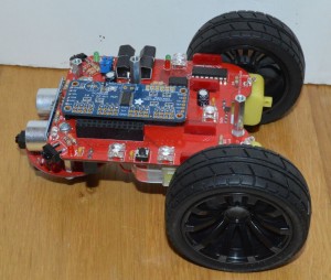
We have created a python library that makes programming PiRoCon and Initio very simple.

If you are using the PiRoCon on a different robot, you may need to change some of the pin assignments used, but the code itself should be fine

Raspberry Pi Python examples can be downloaded from an LXterminal session and connected to the internet, type in or copy and paste:

wget http://4tronix.co.uk/initio.sh -O initio.sh

Then type in:

bash initio.sh

You will then have a number of python examples to try. Run them with

sudo python filename.py
  • motorTest2.py:  use the arrow keys to move forwards and backwards, spin left or spin right. Space to stop. Use . and , to increase or decrease speed
  • sonarTest.py: Prints the distance in centimetres from the ultrasonic sensor, once every second
  • irTest.py: Prints the state of the IR line and obstacles sensors, every time the state changes.
  • servoTest.py:  use the arrow keys to pan and tilt

Python Software for Pi2Go

Python Software: Library & Examples

If you are setting up a new SD card, please follow the instructions in this PDF

We have created a python library module that allows you to use the same software to drive either the Pi2Go or the Pi2Go-Lite. Some functions can be directly mapped between the two products, but other functions will only work one one model or the other.

  • Download the latest version of the software using wget like this from a command line (eg. LXTerminal):
    wget http://4tronix.co.uk/pi2go.sh -O pi2go.sh
    bash pi2go.sh
  • This will create a new folder on your Pi in the /home/pi folder called pi2go
  • Run the example files using the following (example is for motorTest):
    sudo python motorTest.py
  • You need to use sudo as admin rights need to allow access to the GPIO pins

 **NOTE** The hardware driven servos used on Pi2Go (not Pi2Go-Lite) must be driven using the on-board servo and PWM driver chip shared with the RGB LEDs. See this Adafruit tutorial for driving servos with this chip as it is the same one used in their 16-channel PWM/Servo driver. The Pi2Go servos are on the top four pins of this chip (pins 12 to 15).

Library Functions:

#======================================================================
# General Functions
# (Both versions)
#
# init(). Initialises GPIO pins, switches motors and LEDs Off, etc
# cleanup(). Sets all motors and LEDs off and sets GPIO to standard values
# version(). Returns 1 for Full Pi2Go, and 2 for Pi2Go-Lite. Invalid until after init() has been called
#======================================================================

#======================================================================
# Motor Functions
# (Both Versions)
#
# stop(): Stops both motors
# forward(speed): Sets both motors to move forward at speed. 0 <= speed <= 100
# reverse(speed): Sets both motors to reverse at speed. 0 <= speed <= 100
# spinLeft(speed): Sets motors to turn opposite directions at speed. 0 <= speed <= 100
# spinRight(speed): Sets motors to turn opposite directions at speed. 0 <= speed <= 100
# turnForward(leftSpeed, rightSpeed): Moves forwards in an arc by setting different speeds. 0 <= leftSpeed,rightSpeed <= 100
# turnreverse(leftSpeed, rightSpeed): Moves backwards in an arc by setting different speeds. 0 <= leftSpeed,rightSpeed <= 100
# go(leftSpeed, rightSpeed): controls motors in both directions independently using different positive/negative speeds. -100<= leftSpeed,rightSpeed <= 100
# go(speed): controls motors in both directions together with positive/negative speed parameter. -100<= speed <= 100
#======================================================================
#======================================================================
# Wheel Sensor Functions
# (Pi2Go-Lite Only)
# stepForward(speed, steps): moves the unit forwards specified number of steps, then stops
# stepReverse(speed, steps): Moves backward specified number of counts, then stops
# stepSpinL(speed, steps): Spins left specified number of counts, then stops
# stepSpinR(speed, steps): Spins right specified number of counts, then stops
#======================================================================

#======================================================================
# RGB LED Functions
# (Full Pi2Go only)
#
# setLED(LED, Red, Green, Blue): Sets the LED specified to required RGB value. 0 >= LED <= 4; 0 <= R,G,B <= 4095
# setAllLEDs(Red, Green, Blue): Sets all LEDs to required RGB. 0 <= R,G,B <= 4095
#======================================================================

#======================================================================
# WHITE LED Functions
# (Pi2Go-Lite only)
#
# LsetLED(LED, value): Sets the LED specified to OFF == 0 or ON >= 1
# LsetAllLEDs(value): Sets both LEDs to OFF == 0 or ON >= 1
#======================================================================

#======================================================================
# IR Sensor Functions
# (Both Versions)
#
# irLeft(): Returns state of Left IR Obstacle sensor
# irRight(): Returns state of Right IR Obstacle sensor
# irCentre(): Returns state of Centre IR Obstacle sensor (Full Pi2Go Only)
# irAll(): Returns true if any of the Obstacle sensors are triggered
# irLeftLine(): Returns state of Left IR Line sensor
# irRightLine(): Returns state of Right IR Line sensor
#======================================================================

#======================================================================
# UltraSonic Functions
# (Both Versions)
#
# getDistance(). Returns the distance in cm to the nearest reflecting object. 0 == no object
#======================================================================

#======================================================================
# Light Sensor Functions
# (Full Pi2Go only)
#
# getLight(Sensor). Returns the value 0..1023 for the selected sensor, 0 <= Sensor <= 3
# getLightFL(). Returns the value 0..1023 for Front-Left light sensor
# getLightFR(). Returns the value 0..1023 for Front-Right light sensor
# getLightBL(). Returns the value 0..1023 for Back-Left light sensor
# getLightBR(). Returns the value 0..1023 for Back-Right light sensor
#======================================================================

#======================================================================
# Servo Functions
#
# startServos(). Initialises the servo background process
# stop Servos(). terminates the servo background process
# setServo(Servo, Degrees). Sets the servo (0 or 1) to position in degrees -90 to +90
#======================================================================

#======================================================================
# Switch Functions
#
# getSwitch(). Returns the value of the tact switch: True==pressed
#======================================================================

Pi2Go-Lite Released at CamJam 6th September 2014

Pi2Go-Lite Kits Released for Sale at CamJam

I went to the Cambridge Jam yesterday and was indundated with questions and people wanting to know more about the newly released Pi2Go-Lite kit for the Raspberry Pi. Now available for immediate shipping from here.

camjam01

I also did a brief presentation of the development process I have been through over the last 9 months or so – starting from a mock-up made from modelling board:

mockup01


And progressing through various prototypes to the final full Pi2Go prototype:

finalproto01


Following this prototype, we forked the project so that the full Pi2Go would be manufactured as a fully soldered mainboard using surface mount components and the Pi2Go-Lite would be a reduced feature-set product that could be hand-soldered using surface mount components.


Pi2Go (Full) Update

Now the Pi2Go-Lite kit has been released and the full Pi2Go is about to go for CE testing at an independent lab. Once these tests are passed, we can move to full production. It looks like it will be at least 6 weeks from now.


Pi2Go is now a Registered Trademark

When I arrived home from the Cambridge Lam, I found a letter containing the registration certificate for the Pi2Go trademark. Excellent timing!

pi2go-cert0002


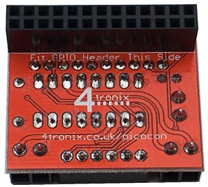
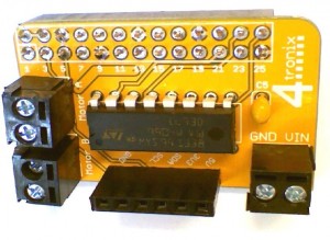
PicoCon – “No Frills” Motor Controller

IMG_0384a

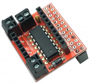
Picocon – The “No Frills” Motor Controller

Purchase Here


Scroll down for the assembly information for v1 of Picocon (Yellow PCB)

Assembling your PicoCon

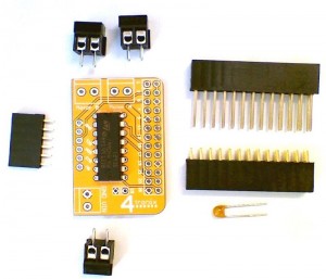
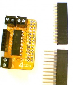
1. Check You Have Everything

IMG_0364b

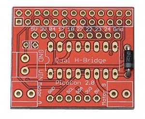
  1. PCB (Red)
  2. 3 x Screw Terminal Blocks
  3. Dual H-Bridge Chip
  4. 100nF capacitor
  5. Diode
  6. 6-pin female header
  7. 10-pin female header
  8. 26-pin female (GPIO) header


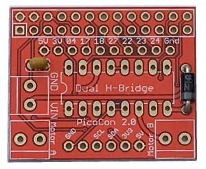
2. Start with the Diode

Step02

Ensure that the white line on the diode is facing the bottom as shown in the photo above. Solder it carefully then snip the leads off underneath


3. Add the Capacitor

Step03

This can be placed either way round. Mount it close to the PCB as shown


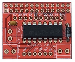
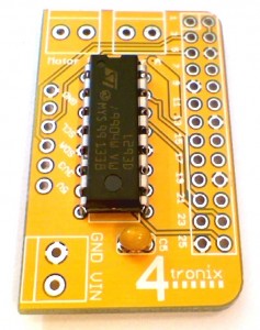
4. Add the H-Bridge Chip

Step04

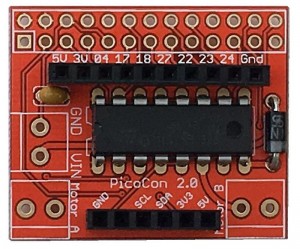
This must be placed the correct way round or it will be damaged. Check the orientation twice before soldering!

The writing ion the chip should be correct way up when viewed as in the photo above. The little ‘U-shaped’ notch should be on the left

Click on the image above to enlarge it to see the orientation more clearly


5. Add the 2 Female Headers

Step05

It is a good idea to add these both at once as the board will rest on them on your desk fairly firmly.

Solder just one pin on each initially. Then pick up and for each header, melt the solder again while holding the header and move it until it is straight and level.

Then solder the remaining pins. It is difficult to straighten them up after more than one or two pins have been soldered, so do it at the beginning.


6. Add the 2-pin Screw Terminals

Step06a

As with the female headers, add them all together so the board rests on them when soldering the first pin of each

Straighten them out before soldering the second pin, in the same way you did for the female headers


7. Finally add the GPIO Header

Step07a

Make sure you add it on the bottom of the board!

Again, just solder one pin at each end then adjust until it is straight. Then solder the remaining pins

Step07b

Your board should now look like this


Software for your PicoCon

1. Basic python software

  • Each motor is directly controlled by two pins, each of which drives one side of the motor
  • To make the motor go forwards, you make one pin high and the other pin low
  • To make it reverse, you make the first pin low and the second pin high
  • For the robot to go forwards both motors should be set to forwards
  • Similarly to go backwards, both motors should be set to reverse
  • If you set the left motor to forwards and the right motor to backwards, the robot will spin right
  • The (physical) pins for the left motor are 19 and 21
  • The (physical) pins for the right motor are 24 and 26
  • So to make the left motor go forwards, set pin19 high and pin21 low. You can do this in python with:
    GPIO.output(19, 1)    # pin 19 is left motor A
    GPIO.output(21, 1)    # pin 21 is left motor B

This is covered in a complete python program picoTest01.py covered below.

2. Using the supplied python library

  • You need to import the library at the start of your python program
    import picocon
  • Then you can use the pre-defined functions for moving the motors:
  • init(). Initialises GPIO pins, switches motors off, etc
  • cleanup(). Sets all motors off and sets GPIO to standard values
  • stop(): Stops both motors
  • forward(speed): Sets both motors to move forward at speed. 0 <= speed <= 100
  • reverse(speed): Sets both motors to reverse at speed. 0 <= speed <= 100
  • spinLeft(speed): Sets motors to turn opposite directions at speed. 0 <= speed <= 100
  • spinRight(speed): Sets motors to turn opposite directions at speed. 0 <= speed <= 100
  • turnForward(leftSpeed, rightSpeed): Moves forwards in an arc by setting different speeds. 0 <= leftSpeed,rightSpeed <= 100
  • turnReverse(leftSpeed, rightSpeed): Moves backwards in an arc by setting different speeds. 0 <= leftSpeed,rightSpeed <= 100
  • To use these functions, you need to preface them with the name of module, picocon.
  • You need to call the function init() at the start of your program to setup all the input and output pins
    picocon.init()
  • You must call the cleanup() function at the end to put all the input and output pins back to where they were
    picocon.cleanup()
  • In between you can do whatever you want, so to make the robot go forwards at a medium speed:
    picocon.forward(50)
  • to spin left at a fast speed
    picocon.spinLeft(100)

Downloading the Software Library and Examples

  1. Make sure the Pi is connected to the internet
  2. From a terminal window on your Pi type the following lines exactly:
    wget http://4tronix.co.uk/picocon.sh -O picocon.sh
    bash picocon.sh
  3. This will create a new folder on your Pi called picocon
  4. Go into this folder and then you can run the examples like this:
    sudo python picoTest01.py
  5. picotest01.py simply goes forwards, backwards, spins right and left in a loop. Press Ctrl-C to exit
  6. picotest02.py does the same thing but using the library (see how much simpler the code is)
  7. picotest03.py uses the arrow keys on your keyboard to move the robot. You can also use . or , to speed up and slow down the robot. Also use space to stop

—————————————————————–

Following information for Picocon v1 (Yellow)


step07a


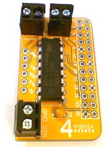
The PicoCon is a very basic “No Frills” motor controller that lets you get going with robots very quickly and simply.


Assembling your PicoCon

1. Check You Have Everything

step01

The are only 7 components to solder to the PCB:

  • L293D Dual H-Bridge chip
  • 3 x Screw Termianls 2-pin
  • Capacitor 100nF
  • 6-way Female Header
  • GPIO Header (short and long pin are provided – select which one to use)


2. Solder in the L293D

step02

Solder the main IC – make sure pin one is in the correct place and do NOT spend too long with the soldering iron held against a pin as it may damage the chip. 2 to 3 seconds at most


3. Add the 100nF Capacitor

step03

Add the small capacitor. It doesn’t matter which way around this goes


4. Fit the Screw Terminals

step04

Then add the 3 screw-terminal blocks for the 2 motors and the motor power


5. Fit the 6-Pin Female Header

step05

Connect the 6-pin I2C breakout connector (Very useful if you want to plug in the IP Display so you know the IP address of your robot)


6. Select the GPIO Header to use

step06

If you use the extended header, then it allows you to easily access the GPIO pins not used by the Picocon itself. However, it then makes the Picocon very easy to short out and much more delicate. Choose wisely!


7. Attach the GPIO Header to the UNDERSIDE of the PCB

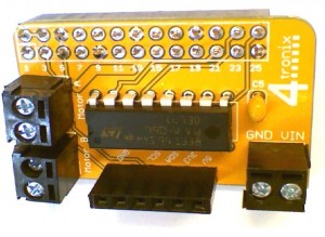
step07a

step08

Finally solder the GPIO head to the REVERSE SIDE of the board. Once on, it is very difficult to remove. So make sure you get it right