Talon Grabber for BitBot, BitBot XL and Robobit Buggy

Purchase Talon here
Assembling Talon for BitBot and BitBot XL
Images show the Classic BitBot version. The BitBot XL version is identical except for the shape of the PCB.
Step 1 – Ensure you have all the parts

Your kit should contain:
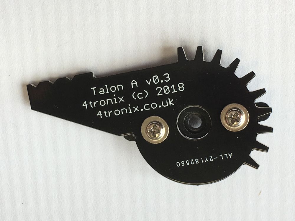
- 3 x PCBs: Talon Base, Talon A, Talon B
- 10 x Screws: M2.5, 6mm
- 2 x Screws: self-tapping 6mm (there are also longer ones in the servo bag – ignore these)
- 1 x Screw to attach servo arm to the servo (this is in the servo bag)
- 1 x Metal gear servo (with various servo arms and screws
- 1 x M3, 12mm, male-female pillar
- 1 x M3, 6mm screw
- 1 x M3 nylock nut
- 1 x Pimoroni spanner widget to help tighten nylock nut
- 4 x M2.5, 12mm pillars to attach to Bit:Bot
Step 2: Attach the Pillar for Floating Jaw
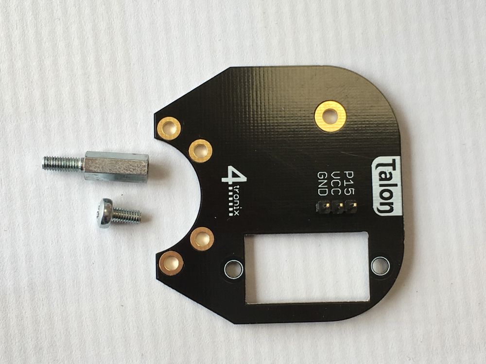
You will require the Talon Base PCB, M3 screw and M3 pillar
Fit the screw through the side of the board shown above and screw tightly into the female end of the pillar. Ensure this is firmly attached
Step 3: Fit the Servo to the Talon Base
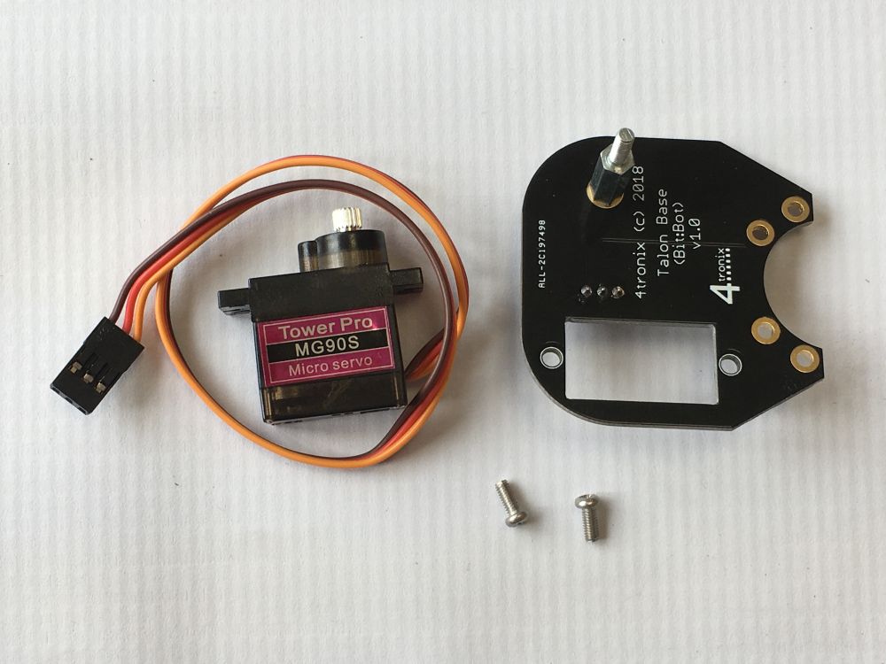
You will need the servo and 2 of the M2.5, 6mm screws

Ensure the servo is positioned on the opposite side of the PCB to the pillar, and the shaft of the servo is in line with the pillar.
Pass the screws through the holes in the PCB and tighten into the flanges of the servo

Turn the PCB over and take the servo wire
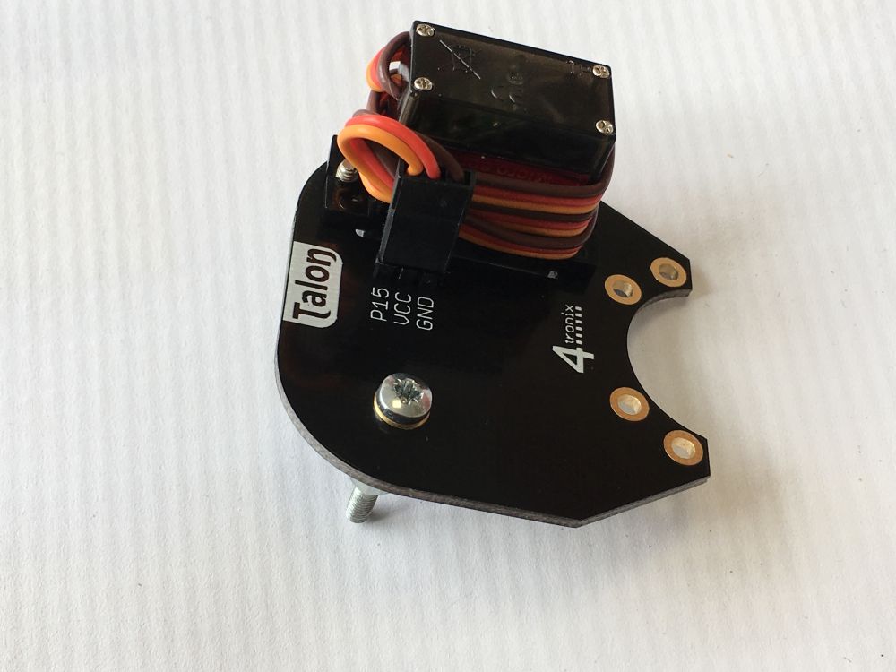
Wrap it around the servo twice then plug the end into the 3-pin connector. Brown wire to the pin labelled GND, Red to VCC and Orange to P15
Step 4: Fit the Floating Jaw
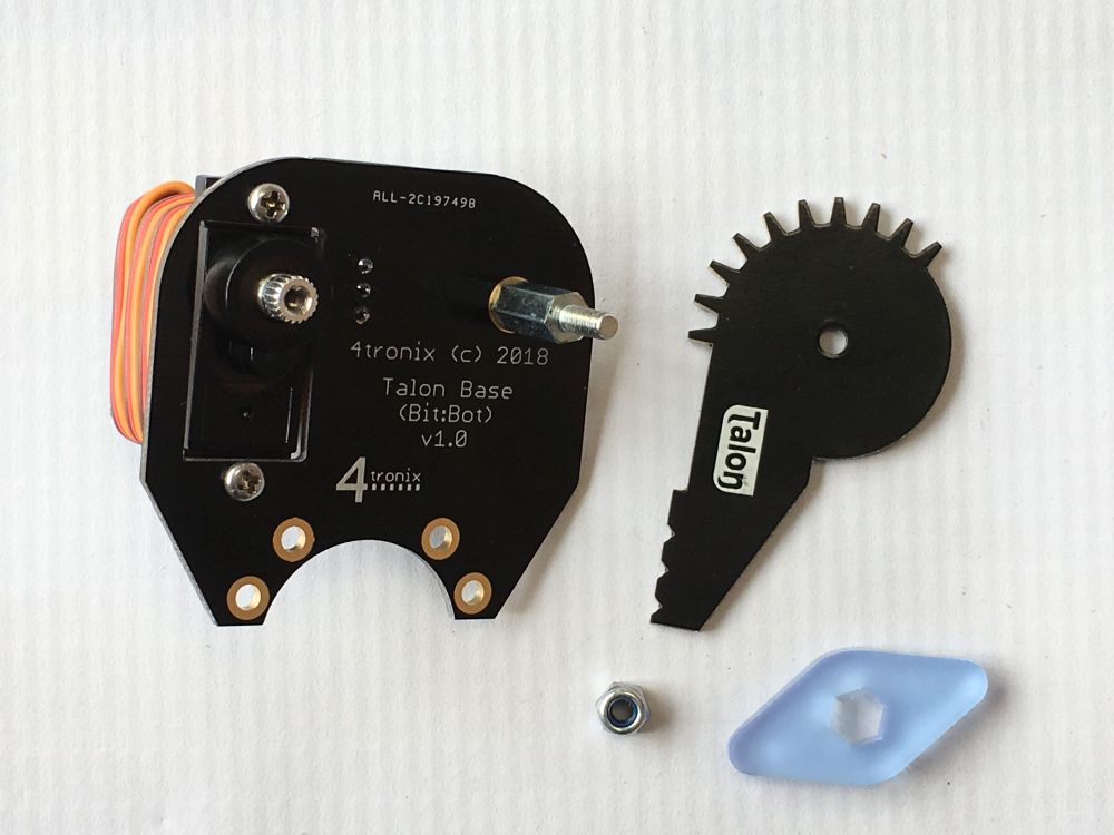
You will require Talon B and the M3 nylock nut.
Fit the Talon B board onto the pillar so the the Talon logo is facing towards the talon Base PCB
Then screw on the nylock nut all the way, then undo it about quarter of a turn until the Talon B jaw can move freely without wobbling up and down

Step 5: Fit the Servo Arm to the Driven Jaw

You will need Talon A, the straight servo arm (from the servo bag) and the 2 small self-tapping screws (not the longer ones in the servo bag)
DO NOT pass the large shaft on the servo arm through the PCB. This shaft needs to be facing away from the PCB.
The screws then pass through the PCB into the Servo Arm and should be tightened.

Do NOT fit this arm to the Talon assembly yet. We need to get the servo working from the Bit:Bot first
Step 6: Fit the Talon Assembly to the Bit:Bot

You will need the 4 M2.5, 12mm pillars and 4 of the M2.5 6mm screws
Screw from the bottom of the Bit:Bot into each pillar, and tighten well. The pillars should be point upwards
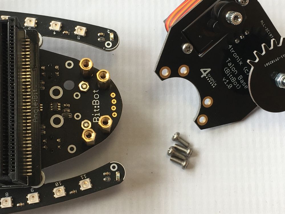
Then using 4 more of the M2.5, 6mm screws, attach the Talon assembly to the top of the pillars.

Note that the servo should be at the top and the floating jaw at the bottom

Step 7: Fit the Driven Jaw (Talon A)

You will need the small screw in the servo bag to attach the drive jaw to the servo.
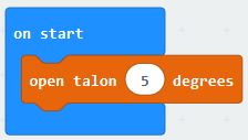
But first: Set the servo to position 5 degrees. If using the Makecode Bit:Bot package, then use the open talon block:
Once the servo is in the correct position, then fit the Talon A jaw, making sure it is closed and is interlocking with the floating jaw (Talon B)

Screw the little screw into the servo shaft to hold it in place
All done! Now you can open and close the jaws by setting the claw/talon to different values between 0 (fully closed) and 90 (fully open)