Cube:Bit
Magical RGB “neo-pixel” Cubes of awesome
Purchase Cube:Bit here
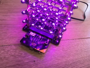
The Cube:Bit collection is a range of 3D “neo-pixel” compatible cubes that are easily built from individual 2D slices.
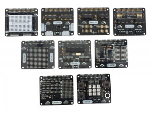
The current range consists of 3×3, 4×4 and 5×5 slices together with a base unit that allows power to be added easily (big cubes can use a lot of power), and also allows a Micro:Bit or Raspberry Pi Zero to be plugged in directly. Of course you can use the Cube:Bits without the base and with any microcontroller thats supports neopixels: Arduino, Raspberry Pi, even Crumble (although the Crumble only supports up to 32 pixels at present, so only the 3x3x3 Cube:Bit can be controller)
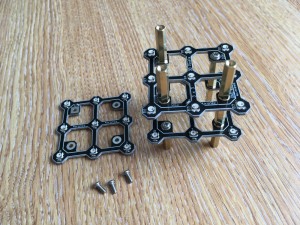
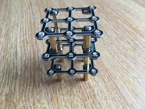
Assembling the cube is easy with threaded rods in each corner providing the structural strength as well as the electrical connections.
Programming it is equally simple as these just appear as a string of neopixels, so use your favourite neopixel driver for your controller.
For the BBC Micro:Bit we have developed a MakeCode package that allows you to use the Cube:Bits extremely simply as well as giving you full x,y,z control of each pixel.
Assembling a Cube:Bit
The basic construction method is:
- Place the 1st slice A-Side up
- Place second slice B-Side up, ensuring Vcc/5V and Gnd are in correct place
- Place third slice A-Side up
- Continue placing slices as required, alternating A-Side and B-Side
- Each Slice has a DOUT (Data Out) from the lower slice connected to its own DIN (Data In) connection. This means that there is a “free-hanging” female-female pillar which is alternately on the left and then on the right, with a matching gap in the vertical pillars on the opposite side
- You can stack these as high as you want – no need to limit yourself to a simple Cube – but watch the power requirements!
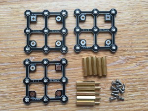
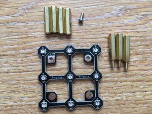
Step 1 – Check you have all the bits
3x3x3 – 3 slices, 5 female-female pillars, 5 male-female pillars, 10 screws
4x4x4 – 4 slices, 6 female-female pillars, 7 male-female pillars, 12 screws
5x5x5 – 5 slices, 7 female-female pillars, 9 male-female pillars, 14 screws
The construction method is the same for all Cube:Bit sizes. Just keep going upwards as you add more slices
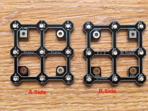
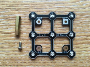
Make sure you can tell which is Side A and which is Side B for each slice (These are more clearly labelled on release version):
- Side A has the names for each LED as 0, 1 , 2, 3, etc.
- Side B has the names as B0, B1, B2, etc.
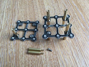
Step 2 – Add Pillars to bottom slice
You will need 4 female-female pillars for underneath, and 3 male-female pillars and a screw for the top
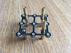
Make sure you have the slice with the A-Side upwards, then fit a female-female pillar below the DIN connection (next to LED 0) using the screw
Fit the other 3 female-female pillars using the male-female pillars to hold them in place
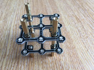
Step 3 – Prepare the Second Slice
Make sure the slice is B-Side upwards, then take a female-female pillar and a screw and fit the pillar on top of the slice in the DOUT connection (next to B8, B15, or B24 depending on your cube size)
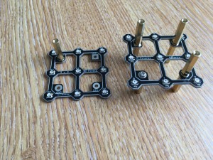
Step 4 – Fit the Prepared Second Slice
Use 2 male-female pillars and a screw.
IMPORTANT: Make sure you place Vcc/5V on this slice directly above Vcc/5V on the slice below.
Screw the pillar from the DOUT of the lower slice into DIN of this slice using the screw
Then use the male-female pillars to attach the remaining 2 pillars from below
Now repeat steps 3 and 4 as often as required, remembering to alternate A-Sides and B-Sides as you stack the slices
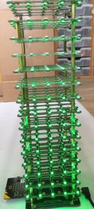
In fact you can keep going as high as you like to make a tall tower – this one is 5 x 5 x 15 slices high
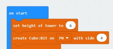
TIP: If you are using the Makecode extension, then there is a block called “set height of tower” that you should use before the “create cube:bit” block
Access this block from the …more category within the Cubebit extensions
Step 5 – Fit the Top Slice
Back to A-Side upwards (assuming 3x3x3 or 5x5x5).
Use three screws to fit the top slice, ensuring that it is DOUT that is NOT connected and that Vcc of this slice is still above Vcc of previous slice
You now have the completed cube on legs as well as spare screws/pillars.
Final options at this point are:
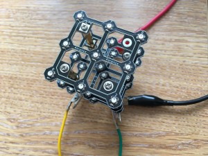
- Leave as is and use croc clips (alligator clips) to connect to the legs for 5V, Ground and Signal
- Connect to the base using 4 of the spare screws. Make sure you connect 5V and Vcc
- Remove the bottom legs and change the first pillars to female-female held in with screws. This makes a tidy cube, then connect to it using soldered wires or tags, etc.
Powering Your Cube:Bit
These cubes have a lot of LEDs and LEDs require power. The 3x3x3 has 54 LEDs and the 5x5x5 has 250 LEDs. On full brightness with White colour this will be several amps.
You _can_ drive them with a low current as long as you set the brightness down low (40 or less) and you don’t set a lot of LEDs to white. This is perhaps suitable for the 3x3x3 cube.
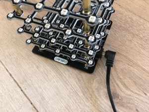
I recommend however using the base and supplying power either via the USB connection or the DC jack connection. There are other connectors on the base as well. Make sure you have changed the jumper to select the power input you are using!
Example currents used (powered by 5V)
- 3x3x3 all LEDs at Red, brightness 40 (out of 255) – Current 150mA
- 3x3x3 all LEDs at White, brightness 40 – Current 340mA
- 3x3x3 all LEDs at White, brightness 255 – Current 1.9A
- 4x4x4 all LEDs at Red, brightness 40 – Current 350mA
- 4x4x4 all LEDs at White, brightness 40 – Current 800mA
- 4x4x4 all LEDs at White, brightness 255 – Current 4.5A
- 5x5x5 all LEDs at Red, brightness 40 – Current 680mA
- 5x5x5 all LEDs at White, brightness 40 – Current 1.6A
- 5x5x5 all LEDs at White, brightness 255 – Current 8.75A
These numbers are important. For instance on the microbit you shouldn’t power the LEDs directly.
So use a 2.5A power supply for the 3x3x3 cube, 5A for 4x4x4 and 10A for the 5x5x5. Although if you set the brightness down low etc. then using lower current power supply is possible and we do most of our testing using a 4A supply. If the brightness is set to 40 (the default) then you can use a 3x3x3 cube with 0.5A power supply and a 4x4x4 with 1A.
Connections:
- Signal from controller (eg Micro:Bit) to DIN on the bottom slice
- Ground from controller to GND on bottom slice
- Ground from power supply to GND on bottom slice
- Power from 5V DC power supply to Vcc/5V on bottom slice
Photo above shows using croc clips to connect to the legs. Yellow is signal from Micro:Bit Pin 0, Green is Gnd from Micro:Bit. Black is Gnd from power supply and Red is power from power supply
In the photo above we’re using a 5V DC power supply with a 2.1mm DC Jack connector (centre positive) that connects directly onto the base. The signal and ground from your controller of your choice then connect elsewhere on the base (eg. the croc clip connection or the GVS connector or the 4tronix Playground connector)
Using Cube:Bit with Raspberry Pi
Please follow this blog entry for installation, Cube:Bit python library and examples.
MakeCode for Micro:Bit Extension
There is a Makecode extension that makes it easy to use the Cube:Bit using x,y,z three-dimensional matrix address of the pixels.
The slice is physically laid out with the LEDs snaking from the DIN corner then back along the next row, and so on until it reaches the DOUT corner (ie. along x axis then along y axis). As alternate slices are mounted upside down and rotated, then the snaking goes along y-axis then along x-axis in these slices. So it is much easier to use the built-in mapping block.
To load the package (until it is formally released) go to Advanced (or click on cog icon) then select Extensions. In the search box add the URL https://github.com/4tronix/cubebit
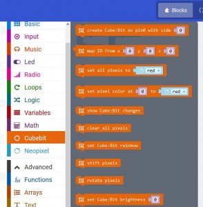
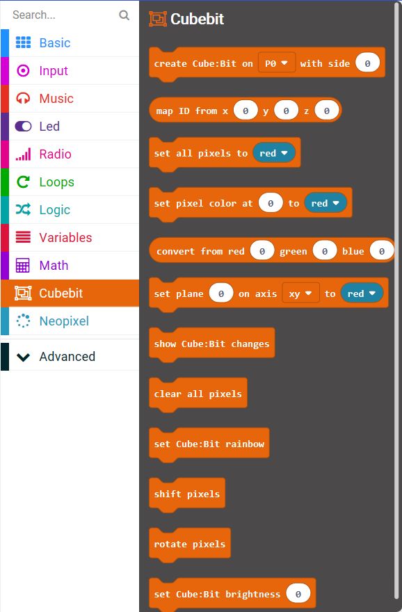
This provides the following blocks:
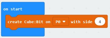
Your first block in the start of program should create a cube of the correct size. If you are using the Cube:Bit base then this will connect via Pin0, but you can change this when not using the base. This will create a string of neopixels of the correct length for your cube and set the brightness to the default of 40. If you want, you can change the brightness with the “set Cube:Bit brightness” block, anywhere from 0 to 255 (255 is the brightest)
You can then write a colour to any or all of the pixels in the cube. eg set (x,y,z) 2,3,0 to Blue when Button A is pressed
Note that this is using the map block to convert x,y,z co-ordinates to a Pixel ID
Note also that the show Cube:Bit changes block is required to actually set the LEDs to the new values that you have set.
TIP: Setting LEDs is always a two part process. Make all the changes you want then show the changes on the Cube:Bit. Just making the changes has no effect on the pixels as it only changes internal memory. This is the FIRST thing you should check if your program is not creating the effect you require
There is a block that allows you to write to a whole plane of pixels at one time. Decide which axis the plane lies on and which plane within that axis:
Additionally you can specify exactly which RGB values to use, instead of simply picking one of the predefined colours:
Make a Rainbow
An easy and fun way to start is to create a rainbow effect using the built-in blocks
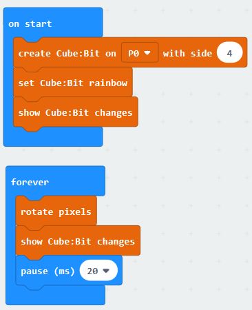
The Start block creates the cube then sets the LEDs to a rainbow scheme (the show cube:bit changes block makes the LEDs match the settings you have selected
Then the Forever block moves the colours all the pixels by one position. Taking the colour of the last pixel and putting it back into the first pixel. This is called rotation. It does this every 20ms so you get an ever-changing colour effect
Example Software
While testing Cube:Bit we have developed a few interesting animations and games for CubeBit
You can download them all from this zip file
Extract the files into a folder on your PC (and remember where you put them)
Then click on Projects, then Import File, then browse to find the file you require.
All examples have a variable called “side” which is set at beginning of the Start block to be 3, 4 or 5 depending which size Cube:Bit you have. Changing the value of side will allow the rest of the program to work correctly and of course affects the way the x, y, z mapping is calculated. You will need to change this line so that it sets the correct size for your Cube:Bit.
- PlaneBounce – this simply lights up a plane and moves it left and right. Coloured Green going right and Red going left
- raindrop – sets a blue/white colour to be rain on the top of the Cube, then drops each pixel to the bottom one at a time and randomly. If you tilt the cube, different planes become the top (at the start of each cycle)
- PurpleRain – as raindrop, but in purple and with a lightning flash at the start and rain recovery animation at the end
- RainSplash – as raindrop, but makes a little splash as each raindrop lands (not great!)
- Revolver – rotates planes in random axis and colours. This works best with larger cubes
- RGBTest – cycles through Red, Green, Blue and White, lighting every pixel on the Cube. A good test of power supply – check the White is actually White and not a yellow/orange colour
- Scan – lights up all LEDs in x, y, z order from 0, 0, 0 to size of the Cube
- TimesCube – builds a small 2x2x2 cube in one corner and grows it to fill the Cube:Bit, then shrinks into a different corner. And repeat
- TicTacToe amd BitCommander – provides a 2 player game of 3D Noughts and Crosses. Install the BitCommander software on the microbit in your Bit:Commander and the TicTacToe software in your Cube:Bit. Use the buttons and dial on the Bit:Commander to move your person around and press on the Joystick to select the pixel you want. The cursor then changes from Red to Green and it is Player 2’s turn. When a line of 3 is made in any direction, the winning line is flashed on and off. Press the Red button on Bit:Commander to start again

