Basic Building Blocks

Basic Building Blocks is a range of soldering kits to make Raspberry Pi add-on boards (aka HATs). The 40-pin GPIO connector is already soldered on all boards (including when you purchase “board only” instead of the complete kit). So you typically only have to add a few components and headers by hand.
Because the boards are very basic, you are not forced down one way of operating. Also, all the boards are sold as bare boards (with GPIO header already fitted) or as a complete kit
In addition, by using an extended female header and appropriate mounting pillars, you can stack these boards together allowing multiple functions simultaneously. Many of the boards have the ability to use different pins for each function by changing jumpers or solder jumpers around.
Purchase Basic Building Blocks here
Download the sample software here
DC Motor
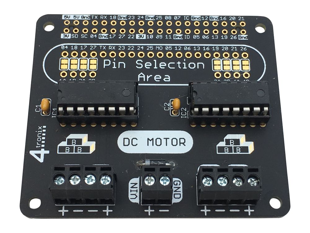

Click on any photo to enlarge
This can be purchased as a Quad motor kit or a Dual motor kit. The Quad motor kit comes with two L293D motor drivers, whereas the dual comes with just one.
Make sure you are adept at soldering. There are plenty of good soldering videos on the web and other resources to get you going.
Solder this kit by fitting the lowest height components first: Diode, then capacitors, then IC sockets, then 2-pin screw terminals.
- Ensure the diode is the correct way round. White band to the left as shown in the photo above
- Capacitors can go either way round
- IC sockets should be placed with the notch to the left to match the position of the silk screen on the board (nearest the words IC1 and IC2 as appropriate). If you only have one L293D (ie. the Dual version) then you can choose which position to use
- The 2 screw terminals for each pair of motors should be clipped together before connecting to the board. Slide the right hand one down the side of the left one and ensure that it forms a smooth joint all round.
- Cut all the pins neatly underneath using side-cutters, not forgetting the screw terminals which could foul on the HDMI header of the Pi if left long
- Insert the L293D driver chips with the notch on the chip matching the notch on the socket
Now you’re ready to go. Plug it carefully onto your Pi and use whatever language you want to control it.
The default pins are:
- Motor 1: 04, 18
- Motor 2: 17, 27
- Motor 3: 19, 20
- Motor 4: 21, 26
These are set by default in the pin selection area. To change them you will need to cut the small track on each solder jumper above the holes labelled 1A, 1B, 2A, 2B etc. Then wire in your choice of pins from the long row of holes above to the 4 holes on each side
Programming motors is easy using GPIO.ZERO
