Crumble – Easy Peasy, Lemon Squeezy
Related Posts:

The Crumble controller is a tiny circuit board, only 33 x 52mm that allows young children (and their teachers) to quickly and very easily learn coding and some simple electronics.
Physically, the Crumble is connected to other components using crocodile leads (“croc clips”), whilst in the software (which runs on a PC and Mac – Linux is coming soon) everything is done visually using drag and drop or simple clicks for selections.
Simple drag the elements you want onto the stage, click on the selections (eg On and Off, Motor1 or Motor2) and press Go. The program is sent directly via USB to the Crumble and starts to run immediately. Even better, the Crumble never forgets its program, so you can power it back up next day or even next year and it will start running the last program downloaded to it.
The hardware is designed very cleverly so the 4 connections labelled A, B, C and D can be either Inputs or Outputs and they will automatically change based on what you use them for in the program. No need to worry younger children with setting things up first, Crumble just works out what they want to do and does it directly.
What Do I need to Get Started?
Ideally, purchase one of our starter kits and include a battery holder. What you need is:
- The Crumble controller itself
- Micro-USB cable
- Optionally – Something to use as an output (eg an LED or two, a motor, Sparkle, etc.)
- Optionally – Something to use as an input (eg. a switch or a light sensor)
- If you want to drive Sparkles or motors, then you will need a battery holder which you can connect to the Crumble using croc clips
- Download the software (PC or Mac available now, Linux coming soon) from here
- We are developing a number of “Crumbs” to use with the Crumble. Currently available or under development are:
- Sparkles – full RGB LEDs
- Slider – Analog input slide controller
- Dial – Analog input rotary control
- Lux – Analog input light sensor
- Motion – Analog input 3-axis motion sensor
- Button – Digital input press button
- Reed – Digital input magnetic reed switch
- Proximity – Digital input proximity detector
- Touch – Digital input touch pads
- Motor – Analog output DC motor
- Number – Analog output Numerical display
- Servo – Analog output positional servo
- Traffic – Digital output LEDs in Red, Amber, Green with PiStop support
- Buzzer – Digital output Buzzer with indicator LED
Visit THIS LINK to learn more about our Crumbs
Hello World – Flashing an LED
You can connect the Crumble outputs (A, B, C and D) directly to LEDs to turn them on and off. Remember the LEDs only work in one direction, so make sure you connect the long lead (positive) to the output terminal and the shorter lead (negative) to the ground terminal (-). You won’t damage anything by putting it the wrong way round, it just won’t operate.

In the photo above, a blue LED is connected from A to the long lead (using the Yellow croc clip) and from the short lead to Ground – terminal (using the Green croc clip)
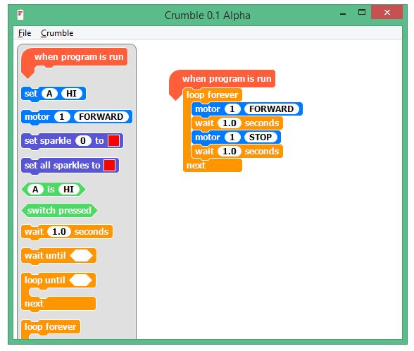
The program to flash it forever looks like this

Setting output A to HI, switches on the LED. Setting to LO switches the LED off. How simple is that?
Now extend this by connecting different colour LEDs to the different outputs (B, C and D) and see if you can make a traffic light sequence!
Doing something with an Input
There are 2 types of input devices that you can use:
- Digital inputs (such as a switch) that can be On or Off
- Analog inputs (such as a light sensor) that can be any value from 0 to 255. (these numbers are arbitrary and chosen by the Crumble designers to match the internal hardware. The numbers do not mean anything in the “real world”, except that 0 is the smallest value and 255 is the largest value)
In the 4tronix standard starter kit we include an LDR (Light Dependent Resistor) which is an analog input device. For this to operate, one end (it doesn’t matter which end) is connected to a positive output and the other end goes to the input. For the positive output you can use one of the (A, B, C, D) terminals – or the 5V (+) terminal if you have power connected from a battery pack. Note that the + terminal is not powered from the USB input, only from a separate battery pack.
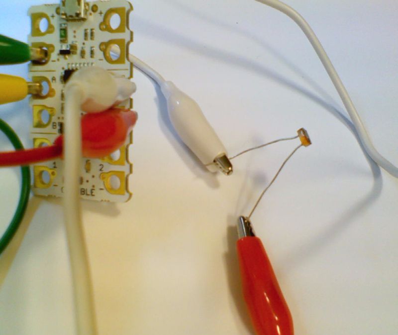
Here red and white croc clips are connected between C, D and the two leads on the LDR. The yellow and green croc clips are still connected to the blue LED from the example above.
The following program uses the analog values (between 0 and 255 remember) to set the delays in the flashing loop. The smaller the number, the faster the LED flashes. The number is smallest when the LDR is darkest – higher numbers for brighter lights.

The first command is to set output D to HI. This provides the positive signal for the LDR.
Note that we have used the “wait … milliseconds” block instead of “wait … seconds”. Waiting 255 seconds between flashes might be too long!
The time to wait between flashing HI and flashing LO is simply the analog value of the LDR. The brighter the light, the bigger the analog value and the longer the flashes.
Driving the Sparkles
Sparkles are individual RGB (Red, Green, Blue) LEDs that can be connecting in a long chain (up to 32 with the current software) and each can be set to a different value. These are also known as “neopixels”. Sparkles require a 5V power connection which can be from the + terminal on the Crumble (if a battery pack is connected) or from one of the A, B, C outputs set to HI. If using one of the A, B, C outputs then you can only use 1 or 2 Sparkles as they cannot provide enough power for more.

In the photo above, we have used output C to connect to the Sparkle’s power + input. The data input of the first Sparkle in the chain must be connected to the D output on the Crumble. This first Sparkle is called Sparkle 0, the next is Sparkle 1 and so on. Each Sparkle must be connected to power and Ground: use the + and -terminals from the previous Sparkle for this. Each Sparkle also needs an input signal. The input for the first Sparkle is the Crumble D output, but after that use the output from one Sparkle and connect it to the input of the next in the chain


You can flash the Sparkles using a simple loop as shown above. Notice the first statement sets C to HI to provide power for the Sparkle. We only have one Sparkle in our chain, so this is Sparkle 0. You can select any colour you like for each Sparkle just by clicking on the coloured square.
Driving Motors
In our Super and Ultimate Crumble kits, we also include DC motors. Again, these can be driven directly by the Crumble, but you must have a battery pack connected for these to work. The mootors use Pulse Width Modulation (PWM) to adjust the speed. Instead of changing the voltage driving the motors, the amount of time that the motor is powered is varied. If it is powered 100% of the time it will go at full speed, but if only powered 50% of the time it will go about half speed (actually, it isn’t quite that, but close enough).
So connect one side of the motor to the motor + terminal on the Crumble (eg. Motor 1) and the other side of the motor to the motor – terminal as shown.

This program loop runs forever and makes motor 1 move forward for 1 second, then backward for 1 second
Crumbs
Slide Crumb – Analog Input

The Slide Crumb is Yellow – this means it is an analog input Crumb
In the software, you can read analog inputs using the  method. This gives a number from 0 to 255 that you can use to set the brightness of Sparkles, the speed of a motor or the rate of flashing of LEDs for example.
The code below sets the brightness of the Red component of a Sparkle

And this one sets the speed of the motor to vary with the position of the slider. Note that the motor speed must be between 0 and 100, so we divide the analog value by 3 so that we don’t exceed the value
