UltraSonic & LED PCB Kit
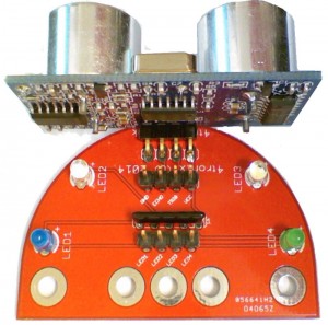
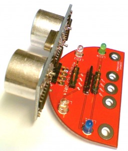
This kit makes it easy to mount a standard SR-HC04 ultrasonic sensor on the front of a robot. The sensor itself is soldered to the PCB which acts as a carrier, additionally having M3 mounting holes at various spacings.
The board also carries 4 LEDs with the necessary series resistors to be driven directly from Arduino or Raspberry Pi GPIO pins.
Click any image to enlarge.
1. Check you have all the parts
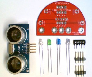
The kit contains:
- 1 x PCB
- 1x UltraSonic sensor
- 1 x Resistor pack (4 x 220R resistors in a SIL package)
- 2 x White LEDs
- 1 x Blue LED
- 1 x Green LED
- 2 x 4-pin male headers
2. Solder the LEDs
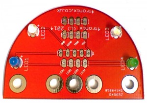
It doesn’t really matter where you put each LED, but the standard way for our Pizazz robot is as shown above.
NB. Ensure that the longer lead (positive) from each LED is soldered into the holes marked with a ‘+’ sign (towards the top of the board in the photo above)
3. Solder the Resistor Pack
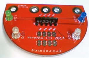
The resistor pack must be placed the correct way round, with the white dot next to the ‘1’ marked on the PCB. The writing is therefore point towards the ultrasonic mounting points as shown in the photo above.
4. Solder the 4-pin Male Headers
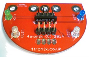
These should be mounted in the positions either side of the resistor pack. To get the straight, I find it easiest to solder just one pin of each header, then holding the board and header in one hand and the soldering iron in the other, gently melt the solder and move the header so it is straight. There’s a bit of a knack to this 😉
5. Finally, Solder on the UltraSonic Sensor
This should be mounted on the same side as all the other components. You can double check, by checking that the writing on the front of the sensors, matches the pins on the 4-pin header next to it. (ie. VCC is next to VCC, Trig is next to Trig, etc)
Again, solder one pin first then straighten it out using the same method as for the headers.
6. The Completed Board – Ready for Mounting on your Robot

