ZeroPoint – Analog Output for your Raspberry Pi

ZeroPoint – Analog Output

IMG_0286a

IMG_0292a


Overview

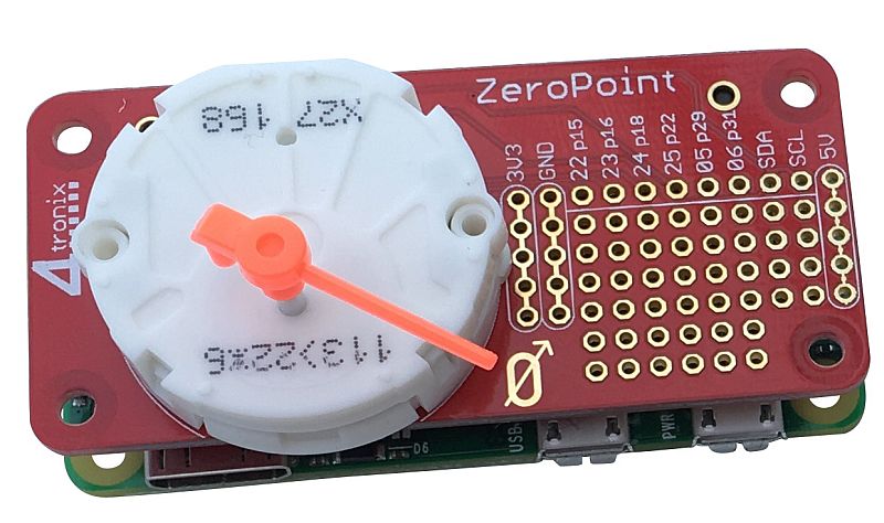
ZeroPoint is an analog gauge with a prototyping area for your own sensors

The gauge is a small stepper motor (X27.168) that is driven using an H-bridge (it’s a bipolar stepper so needs to be driven both ways)

Although it is a standard stepper motor to operate, it only travels through 315 degrees before hitting the physical end stops.

This gauge is used in many vehicles for speedometer, tachometer, etc. and so is in plentiful supply

It is a very weak stepper motor and cannot be used to drive much at all (cue someone trying to use two for a small robot!)

Power is taken from the 5V of the Raspberry Pi, so no additional power is required.


Software

We have a python library which can be used to position the needle accurately. You can download directly the library and example file by typing the following into the terminal window. Open LXTerminal and type:

  • wget http://4tronix.co.uk/zpoint.sh -O zpoint.sh
  • bash zpoint.sh

That will create a zeropoint folder in your home folder, with the library and example file:

  • zeropoint.py  library module for ZeroPoint
  • testPoint.py  a simple test script that allows you to set the position from 0 to 100% by pressing the number keys  (and ‘a’ for 100)
  • zeropoint.init ( ) – initialises the various settings and forces the pointer to zero
  • zeropoint.setTo (position) – sets the pointer to position (from 0 to 600)
  • zeropoint.stepToZero ( ) – forces the pointer to the zero position (oversteps to ensure this)
  • zeropoint.cleanup ( ) – closes down tidily, stopping the background stepper thread, shuts down the GPIO handler


Finally, there is a PDF file with a number of dial templates that could be used. Of course you can create your own with your specific measurement values on such as degrees Celsius/Fahrenheit  or humidity etc.

base3

Links


Using the Prototype Area

The prototyping area is intended for you to add you own sensors or input devices so you can create a standalone analog meter. These could be temperature sensors, light sensors, buttons, etc. To help you wire this in we’ve provided:

  • 6 spare GPIO signals (labelled with both BCM GPIO numbers and physical pin numbers)
  • I2C signals
  • Power lines: Ground, 3.3V and 5V (each has a column of 5 holes, all connected together)
  • There is then a bank of 8 x 6 non-dedicated holes for you to put in your own components. NB. 4 holes are missing in bottom right corner to allow space for the mounting hole, giving a total of 44 non-dedicated holes

Ultrasonic Addons for CrumbleBot – Assembly and Use

Ultrasonic CrumbleBot Addons

IMG_0099b

IMG_0098b

Download Updated Crumble software from here

This post gives brief instructions for assembling the Static and Panning versions of the Ultrasonic addon for CrumbleBot

You will need version 25.5 or later of the Crumble Software – see the link above to download it.


Static Ultrasonic Distance Sensor

IMG_0106b

Check you have the correct parts:

  • White base PCB with ultrasonic sensor
  • Red Positive power connection PCB
  • Black Negative power connection PCB
  • 2 x 15mm Pillars
  • 6 x 6mm Screws
  • 2 x Nuts

Fit the Distance Sensor to the CrumbleBot

  1. The Black negative power connector PCB is fitted on the left side of the CrumbleBot with the writing facing upwards.
  2. Use a screw and nut to screw the connector PCB into the hole marked V-. Do not tighten the screw
  3. Screw in the Red positive power connector PCB onto the right side of the CrumbleBot using a screw and nut into the connector marked V+. Don’t tighten the screw.
  4. The other ends of the two power connectors PCBs should line up with the 2 mounting holes at the front of the CrumbleBot
  5. Now use 2 more screws to fit the 15mm pillars onto the top side of the CrumbleBot, feeding the screws through the mounting holes, through the power connector PCBs and into the pillars
  6. Finally, use the 2 remaining screws to fit the main ultrasonic sensor board to the tops of the 2 pillars
  7. Now tighten all the screws so everything is fixed tightly
  8. It should now look like the photo below

IMG_0098b

Using the Static Distance Sensor

  • Ensure you have downloaded the latest version of the Crumble Software (must be at least v25.2)
  • Use a crocodile clip cable to connect one of the inputs (A, B, C or D) to the connection marked “SONIC” on the sensor board
  • Use the “Distance” block and set both ‘T’ and ‘E’ to the same pin as you are using to connect the sensor (The example below shows it connected to input A)
  • The example code below simply gets the distance and saves it into variable t. You can look at the variables and see the distance change as you move your hand in front of the sensor

sonic01


Panning Ultrasonic Distance Sensor

IMG_0103b

Check you have the correct parts:

  • White base PCB with ultrasonic sensor and 4-pin connector
  • Larger White PCB with servo and 4-pin connector
  • Red Positive power connection PCB
  • Black Negative power connection PCB
  • 2 x 25mm Pillars
  • 6 x 6mm Screws
  • 2 x Nuts
  • 4-way Female-Female 10cm Cable (various colours)


Fit the Distance Sensor to the CrumbleBot

  1. The Black negative power connector PCB is fitted on the left side of the CrumbleBot with the writing facing upwards.
  2. Use a screw and nut to screw the connector PCB into the hole marked V-. Do not tighten the screw
  3. Screw in the Red positive power connector PCB onto the right side of the CrumbleBot using a screw and nut into the connector marked V+. Don’t tighten the screw.
  4. The other ends of the two power connectors PCBs should line up with the 2 mounting holes at the front of the CrumbleBot
  5. Now use 2 more screws to fit the 25mm pillars onto the top side of the CrumbleBot, feeding the screws through the mounting holes, through the power connector PCBs and into the pillars
  6. Then use the 2 remaining screws to fit the servo board to the tops of the 2 pillars
  7. Now tighten all the screws so everything is fixed tightly
  8. Push the Board containing the ultrasonic sensor onto the top of the servo and use the screw inside the servo parts bag to fit it more permanently (actually, you can leave this off until you are sure you have it set to the centre position when the servo is centred)
  9. Finally, use the 4-way cable to connect the Sensor PCB to the Servo PCB. Make sure that the wires do not cross over. So for example, if you have Brown, Red, Yellow Orange at the top, then you must also have Brown, Red, Yellow, Orange at the bottom. (your wires may be completely different colours, so just ensure they are in the same order at the top as at the bottom)
  10. You should now have something like the photo shown below

IMG_0099b


Using the Panning Distance Sensor

  • Ensure you have downloaded the latest version of the Crumble Software (must be at least v25.2)
  • Use a crocodile clip cable to connect one of the inputs (A, B, C or D) to the connection marked SONIC on the servo board
  • Use another crocodile clip cable to connect one of the inputs to the connection marked SERVO on the servo board
  • Use the “Distance” block and set both ‘T’ and ‘E’ to the same pin as you are using to connect the sensor (The example below shows it connected to input A)
  • Use the “Servo” block to set the position of the servo from -90 degrees to +90 degrees. 0 degrees should be straight ahead
  • The example code below sets the servo to straight ahead, then gets the distance and saves it into variable t
  • If the servo is not pointing straight ahead, pull off the top PCB with the sensor on and fit it onto the servo again so it is pointing ahead. Then tighten the screw.

sonic02