Overview

Picobot 2 is an all-new design, but recognisably similar to the original Picobot. Here are some of the key hardware differences:
- Acrylic case for all models
- Built-in LIPO battery and smart charger
- USB interface for programming and charging
- Supports Bluetooth Smart (Bluetooth Low Energy, BLE)
- Supports Wifi using ESP8266 (NB. choice of Wifi or Bluetooth is a build-time option. One or the other, but not both)
- Improved internal power supplies, keeps the ultrasonic sensor running even with low battery levels
- Improved line follower and light sensors
- Fully RoHS compliant
Links
- Purchase
- Assembling
- Pinout PDF
- CH340 Drivers for Windows, Mac and Linux (Windows 7 and later will find them automatically – but may take several minutes to do so)
- GitHub repository with latest library and example code
Child-Friendly Assembly
It is *Really* simple to assemble the Picobot2. All you need is a small cross-head screwdriver and a few minutes.

Above shows all the parts that you receive in the box. Clockwise from top left:
- Picobot2 PCBA ready-assembled with motors
- LIPO battery (with protection circuitry)
- Wheels
- Screws and nuts
- Acrylic case (5 layers)
Visit this link to see the detailed assembly instructions
First Steps
When the Picobot2 is delivered, it contains 5 programs that you can access using the Mode button
1. Flashes the LEDs rapidly
2. Line Follower. Stick black insulation tape down and it should follow it (depends how reflective the surface it is on – fine on wooden floors!)
3. Light Follower. Follows a torch shining on it, but not very well at the moment
4. Obstacle avoider. When comes close to something, it reverses and turns around then moves off again
5. Person follower. Tries to stay at 10cm from an object. I need to slow down the movements as it is too jerky at present and goes off line.
The Mode button (right side, front) changes between these programs. When you press the button it will move onto the next one and flash the Blue LED the right number of times (ie. it will flash 3 times before running the light follower). The obstacle avoider program in particular doesn’t listen to the button very often, so you may have to hold it down for a couple of seconds before it reacts.
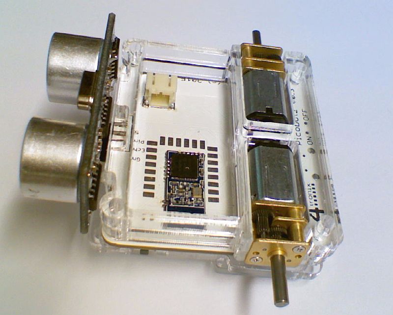
Know Your Picobot2

This image is from an earlier prototype, but gives the general picture – most of the electronics is on the underneath. The light sensors are on top at the front corners
Bluetooth Connection
The Bluetooth is a direct pass-through, with a small set of AT commands. So don’t start a packet with AT or it will be interpreted as a command. In the Arduino code you can open the software serial connection at 9600 baud, then read or write from it directly.
#include <SoftwareSerial.h> SoftwareSerial BLE (2, 3); // RX, TX BLE.begin (9600); BLE.println (“Hello world”);The AT commands are listed here
iOS (8 or later): Use LightBlue app from the AppStore to find and listen or send data to the Picobot2: Tutorial
Android: Use the WIreless-Tag agg referred to in page 14 of the Bluetooth module specification here
ESP8266 Connection
There is an ESP-12E module used for WiFi and it is controlled via the Software Serial interface using AT commands.
With these AT commands you can connect to an existing WiFI network, create your own access point, or both. You can easily create a web server so that anyone with a WiFi enabled smartphone or PC can attach to your Picobot2 and control it, or simply receive updates about the sensors and what the Picobot2 is doing. It’s entirely up to you.
The AT commands are listed here
Latest Status
21st December: Released: Purchase here
- Picobot2 is now released
- Production capability is very limited at around 10 units per day, so if you order several there may be a delay before they are shipped
- The second batch should be factory-produced and thus shipment in quantity will be possible
- Once factory production is established, Picobot2 will be released to distributors
16th December: Released for pre-Order – Purchase here
- PCBs have arrived as planned – Good News! They work 🙂
- I thought when testing that there was a hardware problem, but after a lot of investigation, it turned out to be a problem with the new Arduino Picobot2 library code
- This has delayed full testing, so there are things still to test such as Bluetooth, WiFI, voltage regulation, etc, but all is looking good so far
- Now it is time to start planning the shipping roll-out. We’ve sold more than was expected so it is likely that later orders may not ship until the new year
- We close for new orders on Monday 21st December, but will still ship outstanding paid for orders on 22nd December. After that we won’t be around
- So if all goes to plan we will be able to ship the first order on 17th December. Other orders will follow in the order they were placed
13th December: Released for pre-Order – Purchase here
- We now have the stencil which will enable solder pasting on the blank PCBs when they arrive
- We also have the cases, with the 4tronix and Picobo2 logos etched into the top layer
- PCBs have been manufactured and are on the way from China
- PCBs expected on 16th December and should be tested and confirmed working the same day (cross all fingers, toes and any other appendages you have!)
- So if all goes to plan we will be able to ship the first order on 17th December. Other orders will follow in the order they were placed

Metal foil solder stencil

New top layer with logo etching
3rd December: Released for pre-Order – Purchase here
- For now, we have left off the new accelerometer because, to really be useful, it needs a lot more software support
- Retail pricing (without Bluetooth or Wifi) is £36.00 + VAT
- First production PCBs and cases have been ordered today
- Arduino library code is being tidied up and documented fully
- Still to do: Document use with Snap for Arduino and Blockly
19th November: The (hopefully) Final prototype PCBs due in today. To do:
- Assemble and test the final prototypes
- Decide which components to leave in or out (mainly, do we need the accelerometer?)
- Work out final product cost and set distributor and retail pricing
- Purchase the first small batch (100 units) of PCBs, cases and any other components we’re running short of
- Keep working on software demos and libraries
- Release for pre-order on our web-site