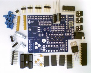
PiRoCon Robotics Controller
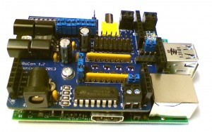
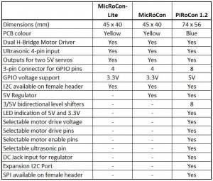
NB. V1.2 PiRoCon controller is now shipping. This has a few minor changes and needs to use the addon name “PiRoConB” in Scratch GPIO 4 onwards to work correctly.
Nomenclature
All connections are referenced by the pin number on the GPIO connector. Most also show the name of the signal as normally used on the Raspberry Pi. For instance GPIO connector Pin7 is called GPIO#04. As there is not much space on the PiRoCon board, we have labelled the 8 free, level-shifted, GPIO pins with an ‘x’ prefix to indicate the GPIO pin number, or a ‘#’ prefix to indicate the GPIO number. So the first pin is x07 (#04).
Connector positions
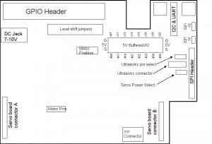
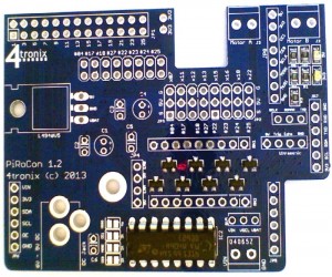
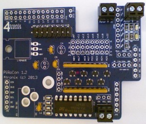
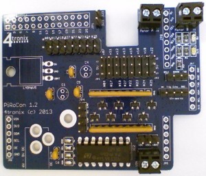
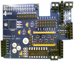
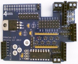
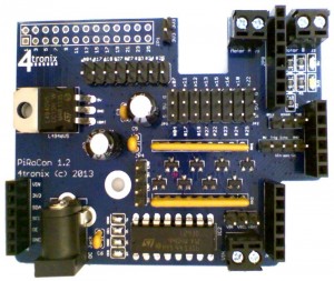
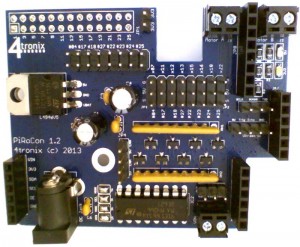
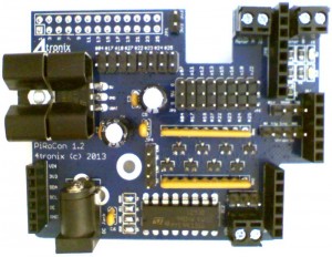
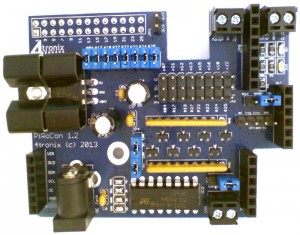
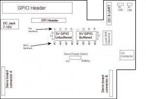
The following drawing shows the position of the major connector blocks. Note especially:
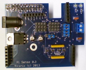
- Row of eight 2-way male header pins with jumpers to feed the “unallocated” GPIO pins into the level shifters – remove the jumper to disable if required
- Row of eight 3-way male header pins. The pins nearest the edge of the board are Ground, the middle row is +5V and the pins nearest the centre of the board are the signal pins
- Row of four male header pins. This is where the HC-SR04 ultrasonic sensor can be attached. Ground nearest the edge of the board, then Echo, Trigger and +5V (Vcc) in that order
- Use the three pins with a single jumper to select which GPIO pin to use for the ultrasonic. Note the error on the silk screen. The pin marked Tx is in fact pin 23, and the pin marked SCL is in fact Pin 8
- The screw terminal Motor A is intended for the left-side motor(s) and Motor B for the right-side motor(s)
- Motor A uses pins 26 and 24 – Scratch GPIO uses 26 as the direction control and 24 as the PWM speed control (for PiRoCon 1.0 this was pins 26 and 21)
- Motor B uses pins 21 and 19 (Scratch GPIO uses 21 as the direction control and 19 as the PWM speed control (for PiRoCon 1.0 this was pins 24 and 19)
- Servo A (Tilt) is on pin 18 and Servo B (Pan) is on pin 22 (these are the right-most connectors on the 8×3 block
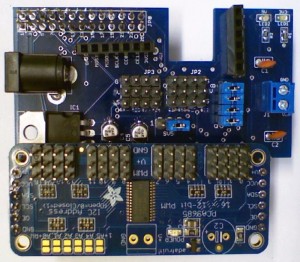
- the two 6-pin female headers near the bottom edge of the board are for plugging in an Adafruit PCA9685 16-channel PWM controller. This is also supported in Scratch GPIO as Servo 1..16
Connecting Jumpers
- Assuming you require all 8 unallocated GPIO pins to use the bi-directional level shifters, then connect a jumper to every one of the 8 pairs of pins on the level shifter jumper block
- There is a 4-way header for the motor driver enable pins. For 2-pin driving of the motor, connect a jumper between the left two pins, and another jumper between the right two pins. (for 3-pin control of the motor, we would use a PWM output from the add-on Adafruit PCA9685 board to driver the enable pins. This has advantages for motor control, but is not used in the basic Scratch GPIO method)
- Connect the ultrasonic select jumper to either left-side (pin 23) or right-side (pin 8). Leave out this jumper if you want to use SCL/TXD for something else. You can then use a female jumper wire to connect the centre pin to your selected pin for the ultrasonic. All our examples use the jumper connected to pin 8 or pin 23
- The final jumper next to the Vin 2-pin terminal selects the power source for the motors. Connect to VBat to use the DC Jack battery input power, or connect to Vin to use the external screw terminal input (this has moved position and function since PiRoCon 1.0 where it was an unused jumper)
Connecting Ultrasonic sensor, Motors and Servos
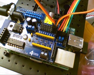
The photo below shows the motors, ultrasonic sensor and Pan/Tilt servos connected. Note the colours for the servos – it is important to get these the correct way around or you may damage the servos. For 4tronix pan/tilt kit, the colours are:
- Brown: Ground (nearest edge of PiRoCon board)
- Red: +5V (middle)
- Orange: Signal (inside pin)
Motor A screw terminal is connected to left-side motor. Motor B is connected to right-side motor.
Ultrasonic is connected directly: Gnd – Gnd, Trig-Trig, Echo-Echo, Vcc-5V
Connecting Wheels Sensors from Initio
The level shifters on the Pirocon are not compatible with the outputs of the wheel sensors, so you must use the wheel sensors at 3.3V and connect the output(s) directly to the GPIO pins. To do this with Pirocon:
- Remove the blue jumpers from the pin(s) you want to use from the block of 8 jumpers. Let’s use #22 and #23
- Connect the Black wire from each wheel sensor to a suitable Gnd pin – you could use the grounds for #22/x15 and #23/x16 as these are not being used otherwise
- Connect the Red wire from each wheel sensor to a 3.3V connection – there are 2 pins near the pin 25 end of the GPIO connector for this purpose
- Connect the Orange (or Brown) wire from each wheel sensor to the pins marked #22 and #23 (where the jumpers were removed)
- You can now read these two pins to get 18 pulses (36 edges) per revolution of each wheel
- If you additionally use the Brown wires from each sensor (you will need to use 2 more pins and remove 2 more jumpers) you can get additional, out of phase, readings for each wheel. This allows you to determine the direction of travel of each wheel as well as speed. When you detect an edge on one signal, then the level of the other signal will tell you which direction the Initio is going
Usage within Scratch GPIO
Note that this requires Scratch GPIO version 4 or later from SimpleSi
Commands available, in addition to the normal Broadcast pin11On, etc. are:
- First you will need create a variable AddOn and set its value to PiRoConB (for v1.0 boards use “PiRoCon”)
- Create a variable called MotorA (and MotorB), then set value from -100 to +100 for speed and direction. -100 is full speed reverse. +100 is full speed ahead. 0 is OFF
- Create a variable Pan (and Tilt), then set values from -90 to +90. -90 is pointing left (or down (up??)), +90 is pointing right (or up (down??)). 0 is pointing straight ahead

