PiRoCon Robotics Controller Kit
Features
The PiRoCon is a controller board for motorised robots. It plugs directly on top of a Raspberry Pi and can be firmly attached using the included pillar and screws (Rev B Pi only). It is designed specifically to drive the 4tronix Initio robot, but it is flexible enough to be used with many different types of robot. Scratch software support is provided by the excellent Scratch GPIO Handler from @cymplecy – Version 4 or later required.

Click on any image to enlarge
The PiRoCon Robotics Controller board includes:
- 5V regulated power supply for the Pi, the board itself and any attached peripherals
- All 8 un-allocated GPIO pins brought out to 3-way headers with power, ground & signal for sensors, etc.
- All of these GPIO include bidirectional, 5V – 3V3 level-shifters
- 2 of these pins can be used to drive standard servos (used on Initio to control the Pan/Tilt mechanism)
- Level-shifters can be removed, or allocated to different pins by removing jumpers and replacing with jumper wire
- A dual H-Bridge is included, connected to to bi-directional PWM controlled motors on screw terminals
- The H-Bridge is connected by default to pins 19, 21, 24 and 26, but can be changed
- A 4-pin connector for the cheap HC-SR04 Ultrasonic range sensor. This is fed, via a resistor network, to a single pin which is jumper selectable between pins 8 or 23
- SPI female header for the SPI pins
- I2C/UART header for the I2C and UART signals
- Red LED for 5V, Yellow LED for 3V3
- Connectors to allow plugging on the Adafruit 16-Channel Servo/PWM Driver using PCA9685 chip. This optional add-on allows PWM control of up to 16 additional servos, or brightness control of 16 LEDs, etc. You can even use 2 of these hardware PWM pins to control the dual H-Bridge using 3 pin mode (where 2 pins control motor direction and the 3rd PWM pin controls speed)
And here is a brief comparison between the PiRoCon and the MicRoCon (his baby sister)

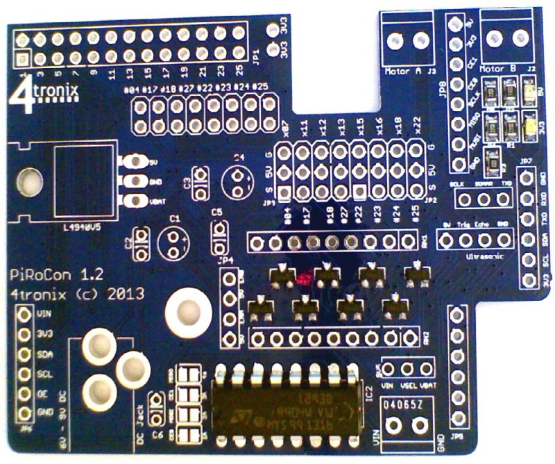
Check you have all the parts
The PiRoCon is delivered as a kit with the following parts. We also offer a soldering service should you want us to solder it for you

- PCB
- All surface mount components are ready-assembled
- 3 off 6-pin female headers
- 1 off 8-pin female header
- 1 off 26-pin GPIO header
- 1 off 3×8 male header
- 2 off 2×4 male headers
- 12 off 0.1″ jumpers
- 2 off resistor networks
- 4 off 100nF ceramic capacitors
- 2 off 47µF electrolytic capacitors
- L4940V5 low drop-out 5V voltage regulator
- L293D dual H-Bridge motor driver
- 3 off 2-pin screw terminals
- DC Jack socket
- 10mm hex pillar with 2 screws and 1mm thick washer (total 11mm required between boards)
- Heatsink with mounting screw and nut
Assembling Process
Starting Soldering
If you haven’t soldered before, you might want to check out this instructable. I find that the following order of soldering works best, starting with the lowest profile components and moving to the highest. This allows me to place the components through the holes in the PCB, then turn the PCB over onto the desk surface and gravity will hold the components in place. You can also use Blutack to hold the components in place while you solder
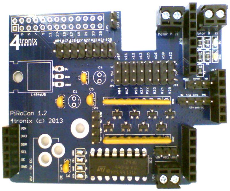
1. Add the L293D Motor Controller Chip
Make sure that pin 1, marked by the little black round indentation and the U-shaped cutout of the chip, is at the edge of the board as shown below
2. Add the 100nF Capacitors C2, C3, C5 and C6
These are small, yellow and marked 104. It doesn’t matter which way round they are put in, but it is neatest if they point the same way. They fit into positions marked C2, C3, C5 and C6

3. Solder across the Motor control pin selections
There are 4 solder bridges to be made. These lie between pin 1 of the L293D chip and capacitor C6. Make sure these are cleanly bridged with no solder traces shorting anything out. If you want to change the pins used to control the motors, then you should remove the solder bridges and connect them to the pins of your choice.

4. Add the Resistor networks RN1 and RN2
These are long and orange. They are polarised and must be connected the correct way round or the level shifters will not work. There is writing on one side only – this writing should be away from the L293D. The dot at one end is pin 1 and this should be in the square at the end of the silk screen markings

5. Solder 2-Pin screw terminals
These are for the motor connections (Motor A and Motor B), and for the alternative source of power for the motor driver – Vin. Make sure you fit them with the screw terminals facing outwards

6. Add the Male header blocks: 8×2 and 8×3
The 8×2 header block is actually made from 2 of the 4×2 headers


7. Add the Male single row headers
There are five of these individual single row headers and are probably the trickiest items on this board to solder neatly:
- The 2-pin header is used for the 3.3V near the GPIO header positon
- One of the 4-pin headers is used for motor enables. The purpose of these is so that you can connect the enable pins for each motor output to a PWM pin as this is the better way to control motors, rather than use PWM on one of the drive pins. The reasoning is fairly esoteric and really makes little difference in practice. But as with many things on the PiRoCon, we provide the option for the customer to experiment
- The other 4-pin header is to connect a 4-pin ultrasonic sensor HC-SR04 directly. All signal condition and converting to single pin operation is provided on the PiRoCon board
- One 3-pin header is used to select which GPIO pin is used for the ultrasonic sensor: Pin 8 or 23
- The other 3-pin header is next to the Vin terminal and used to select whether the battery voltage (VBat) or the screw terminal input voltage Vin is used to power the motors. If you want to power the Raspberry Pi yourself and not use the onboard regulator, you can simply change this jumper to connect to Vin and not use the DC jack battery input

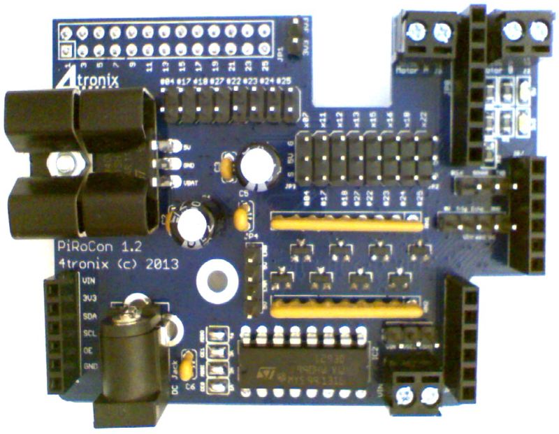
8. Add the Female headers JP5..JP8
There are 4 female headers; 3 are 6-pin and 1 is 8-pin
- JP5 and JP6 (both 6-pin) are used for the I2C expansion port. You can plug Adafruit’s 16-channel PWM board directly in here. Also the 4tronix ADC/DAC board and other boards are planned for the future
- JP7 (6-pin) is the general purpose I2C expansion that also carries the RXD and TXD serial pins
- JP8 (8-pin) contains the SPI pins
- All 4 headers have 5V, 3.3V and Gnd available
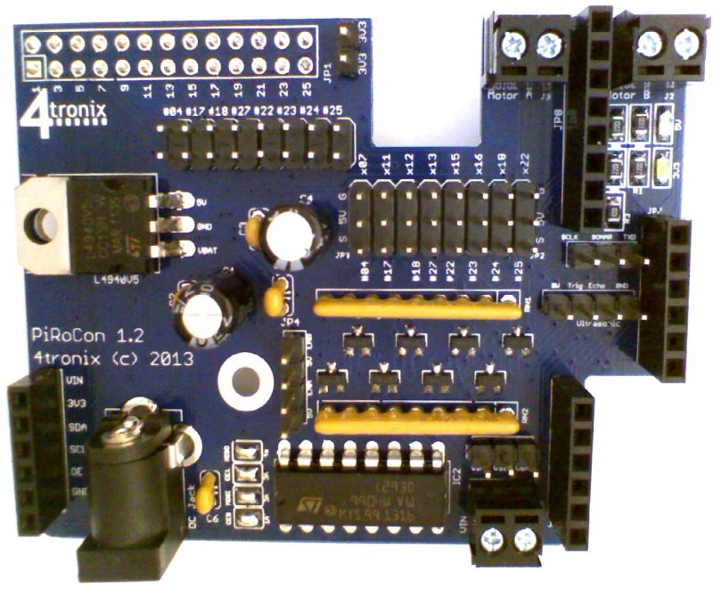
9. Solder the voltage regulator
The L4940V5 is a low dropout regulator that will work happily down to a 6V input and so can be used with 4 AA alkaline cells up to 6-cells of rechargeable NiMH. Solder it in vertically with the legs as far through the board as they will go, then bend it over backwards and you should find that the hole in teh regulator lines up with the hole in the board. If not it can be moved around a mm or so

10. Add the 47uF Capacitors C1 and C4
These are polarised and must be placed the correct way or magic smoke will appear. The long lead is positive and should be placed in the hole marked with a ‘+’ on the PCB. The casing has a grey band with down arrows next to the negative pin

11. Add the DC Jack

12. Solder the GPIO connector to the Bottom of the board
Make sure you solder this to the correct side of the board!

13. Fit the heatsink to the regulator
You will need to push the heatsink onto the regulator then adjust its position so the holes in PCB, regulator and heatsink line up. I find that poking a small screwdriver through the holes allows me to move around the components until the line up correctly. Then push the M3 nut inside the heatsink and screw in the M3 screw from teh bottom of the board
14. Attach the 12 Blue jumpers
These are used for various selections: ultrasonic pin, motor voltage input, motor enables (2) and level shifter selection (8)

15. Attach the Mounting spacer and fix to your Raspberry Pi (Rev B only)
To give a robust mounting of the PiRoCon onto the Raspberry Pi, we provide a metal spacing pillar 10mm and a 1mm thick washer. The spacing between the Pi and the board should be 11mm with this type of GPIO header, so both the metal spacer and the nylon washer should be used as shown below. If there is already a screw holding the Raspberry Pi to a case or similar, then you can remove the nylon washer to give the correct spacing for it to rest on top of the existing screw head

16. Download code from our GitHub
- MotorTestB.sb Allows control of the motors using arrow keys (ScratchGPIO)
- PanTiltTest.sb Allows moving the pan/tilt assembly using arrow keys (ScratchGPIO)
- UltraSonicTest.sb Shows operation of the UltraSonic sensor (ScartchGPIO)
- TrackerTest.sb Uses the ultrasonic sensor on a Pan/Tilt assembly to follow (ScratchGPIO)
- Avoider.sb Uses IR obstacle sensors and motors to avoid objects (ScratchGPIO)
- InitioTest.sb Uses line sensors, obstacles sensors and motors (ScartchGPIO)
- motors.py Python program to show motor operation