Bit:2:Pi Control Raspberry Pi Addon Boards with your Micro:Bit
[Click on any image to enlarge]
Purchase >HERE<
Overview
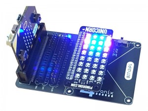
Bit:2:Pi (Pronounced Bit – to – Pie) is a connector and power management system that allows you to plug in a Micro:Bit at one end and a Raspberry Pi addon board (26-pin or 40-pin, HAT, pHAT or other) at the other end.
In between there are some breakout and connection headers that enable you to customise how the two boards are connected.
The power on the board is managed so that:
- Any or all power sources can be connected safely at the same time
- The Micro:Bit is never used to power the Raspberry Pi HAT (this is true for Bit:2:Pi v1.0 or later)
- Power for the HAT is provided either by the micro-USB connector at the HAT end, or by an attached battery holder
- The On/Off power switch controls the power to the HAT as well as to the Micro:Bit
- The “5V” signal on the HAT connector is actually from the battery or the micro-USB. If using the battery, this is likely to be around 4.5 to 4.8V using alkaline batteries, or 3.6 to 4.0V using rechargeable batteries. Not all HATs will work at these voltages.
To control the Raspberry Pi addon board (shortened to “HAT” from now on), you must write some code for the BBC Micro:Bit:
- Many HATs are simply setting GPIO pins High or Low and for these you can use any available language easily. Simply set the Micro:Bit pin corresponding to the HAT GPIO pin (as determined by the various jumpers)
- Some HATs use neopixels (eg. PlayHAT or Unicorn HAT). These require the neopixels to be driven by GPIO18 (physical Pin 12). By default, this is Pin 2 on the Micro:Bit
- Some HATs require I2C commands (eg. Picon Zero). You can use the standard I2C commands within Micro:Bit to send and receive the necessary data. The default configuration connects the I2C pins
- Some HATs require SPI connections (eg. various Analog boards using the MCP3008 or similar). Again the SPI pins are connected by default
Configuration
The male header block closest to the Micro:Bit (labelled MBit/RPi in v1.0) is where most of the configuration is done.
The MBit side of the header is labelled with the Micro:Bit pin numbers and the RPi side of the jumper is numbered with the GPIO names (Broadcom names)
The Bit:2:Pi is supplied with 13 little black jumpers that connect across from the MBit side to the RPi side. This gives the default settings as follow:
|
Micro:Bit Pin |
GPIO Pin |
Physical Pin |
|
0 |
04 |
7 |
|
1 |
17 |
11 |
|
2 |
18 |
12 |
|
8 |
27 |
13 |
|
12 |
22 |
15 |
|
16 |
23 |
16 |
|
5 |
24 |
18 |
|
11 |
25 |
22 |
|
13 |
SCL |
5 |
|
14 |
MISO |
21 |
|
15 |
MOSI |
19 |
|
19 |
SCLK |
23 |
|
20 |
SDA |
3 |
If you need to connect something differently, then simply remove the appropriate black jumper(s) and use a short Female-Female dupont wire to connect theMicro:Bit pin(s) to the appropriate Raspberry Pi pins.
Example Boards
[this section requires tested boards with example code – contributions welcome]
Some tested working boards are:
- Picon Zero
- PlayHat
- PiStop
- Unicorn (HAT and pHAT)
- Explorer
- Pibrella
- CamJam Kit3 Motor Controller
External Contributors
Several people have written some software for the Micro:Bit to work with Raspberry Pi addon boards using the Bit:2:Pi adaptor. Many thanks go out to these contributors!
Michael Rimicans (Twitter @heeedt)
Neil Avery (Twitter @veryalien)
Les Pounder (Twitter @biglesp)
Mark Atkinson (www.multiwingspan.co.uk)

