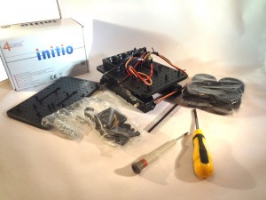
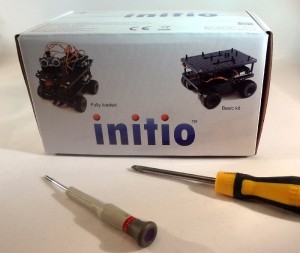
 Initio in box and philips head Screwdrivers
These are all the tools you will need to complete the robot.
You may also want a pair of side-cutters to remove some of the extra mounting
Main chassis with motors, gearbox, battery box and wiring
Top plate
Bag of plastic parts: pillars, standoffs, offset standoffs
Various screws
4 wheels with “SuperGrip” treads
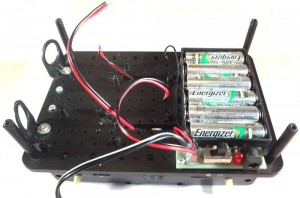 Step 1: Add the vertical pillars by screwing from underneath with the wide-head screws
It’s a good idea to add the mounts for the obstacle sensors and line sensors if you have them.
Step 2: Screw the top plate on using the remaining 4 wide-head screws.
The pillars marked with red circle are where the Model A/B Pi will mount
For a Model A/B you will need to snip off some of the unused pillars so they don’t touch components on the Pi, but this is not necessary for a B+ if you use the adaptor plate
Feed the wires for the motors up to the top
Step 3: For Model A or Model B S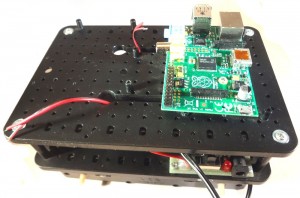 crew the Pi into position with 2 screws.
If you have used the correct mountings then the Pi will have the SD card slot above the On/Off switch
For most purposes you can use a Model A as easily as a Model B.
Step 3: For Model B+
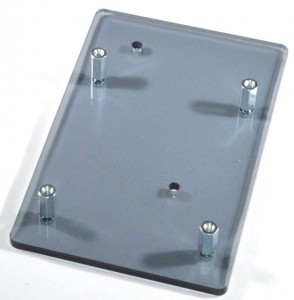
Use the included adaptor plate (Only for Initio shipments after 20th September 2014). You should screw the 4, 10mm pillars into the plate using 4 of the screws provided, then screw the plate to the Initio using the same holes as for a ModelA/B. There is no need to snip any mountings off in this case.
Alternatively (also for shipments before 20th September 2014) you can use 1 fixed mounting for the top right hole, and use one of the small offset mounts for the bottom left hole. You will need to snip of some of the mountings for this arrangement.
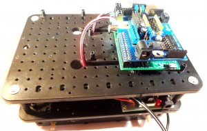 Step 4: Now attached the PiRoCon by pushing carefully onto the GPIO header. If using a Model B+ with Pirocon v1 then you will need to attach the extended header (provided) to the PiRoCon before plugging into the Pi. You should also use the 12mm male-female hex pillar to extend the pillar length to match. For Pirocon v2 it will fit directly to the Model B+. All other instructions remain the same
Ensure that all pins are plugged in correctly as damage will ensue if you plug it in wrongly
Use the 10mm hex spacer and 1mm washer provided to allow the PiRoCon to rest securely on top of the Pi’s mounting screw
An alternative when using a Raspberry Pi Model A/B is to use a Male-Female hex spacer. Screw the male end through the Pi and into the mounting pillar (you will need to drill this to 3mm). Then you can fit the 1mm nylon washer and screw the PiRoCon onto the pillar. It is all mounted firmly and can only be removed with a screwdriver.
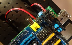 Step 5: We can now attach the motor wires to the PiRoCon terminals
Motor A for the left motor and Motor B for the right motor
The wires are colour-coded so that we know which way is forwards. The correct order is Red-Black-Black-Red as shown below. (note that “black” is actually a “black and red” wire)
This can be tested with the MotorTest script at this point if you like.
 Step 6: Attach the Pan/Tilt assembly
Head on over to >here< for the assembly instructions if you haven’t already built the pan/tilt assembly
The ultrasonic sensor is attached to the clip-on pan/tilt mount by the included small saddle clamp and small screws. In fact the saddle clamp is designed to clamp the 30cm female-female cables, enabling the sensor to be plugged and unplugged at will. You will have received the correct number of wires, but they may not be the same colours. Remove 4 wires from your strip of 10 (for most kits).
Test with the UltrasonicTest script
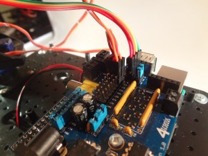 Step 7: Plug in the servos for the Pan/Tilt assembly
Pan servo is attached to x22/#25 on the PiRoCon board. Tilt servo is attached to x18/#24
Be very careful to ensure correct orientation of the servo connector or the servo will be damaged. The Brown wire is Ground and should be connected to the pins marked G. Orange wire is signal and should be connected to a pin marked S. Note that Pirocon v2 has the G pins near the centre of the PCB, while v1 has the G pins nearest the edge.
The ultrasonic cable should be plugged into the 4-way male header matching the signals on the sensor: 5V – Trig – Echo – Gnd with 5V nearest centre of PiRoCon board and Gnd nearest the edge. All these are marked on the PCB – just be careful.
Test with the PanTiltTest script or the Tracker script
Step 8. Adding Line Sensors and Obstacle Sensors
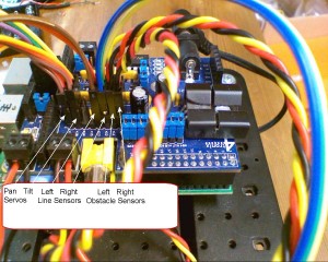
This is enough to test most of the system. You can now add line sensors and obstacle sensors if you have them. You can attach these to any of the 6 remaining 3-way positions. Reading the sensor on the selected pin can be done in Scratch GPIO or Python very simply using the Pin or GPIO number labelled next to the connectors chosen.
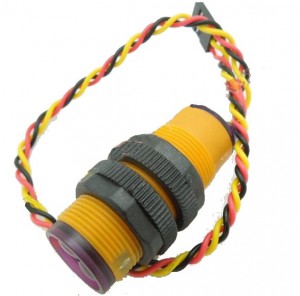
Obstacle Sensor: These are fitted at the front of the Initio, through the round mountings. Point one slightly left and the other slightly right. They come with ready-made cables so can be attached directly to the PiRoCon. Again, ensure that the Black wire is connected to a pin marked G (for Gnd) and the Yellow wire is connected to a pin marked S (for Signal) on Pirocon.
NOTE: It appears that a batch of these has been shipped with only one mounting collar per sensor. Please contact us if you don’t have 2 per sensor and we will ship the other. While waiting for the missing collars you can fit the sensors loosely in the mounting brackets and still operate them successfully.
Line sensor: These are mounted on the end of the 40mm black pillars so that each sensor is about 1cm above the ground. Use the long Female-Female cables to connect them to the PiRoCon.
We find it is best to use the hole nearest the middle of the sensor for mounting them, but it’s up to you.
For example software we’ve created, we have used the following connections for Line and Obstacle sensors:
- Left Line sensor: x12/#18
- Right Line sensor: x13/#27
- Left obstacle sensor: x07/#04
- Right obstacle sensor: x11/#07
PiRoCon Motor Power setting
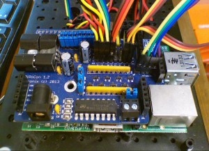
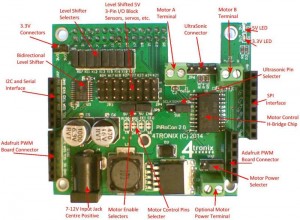
When using the DC jack from the Initio to power the PiRoCon, you should ensure that the motor power selector jumper is nearest the edge of the board as shown in the bottom right of the photo below:
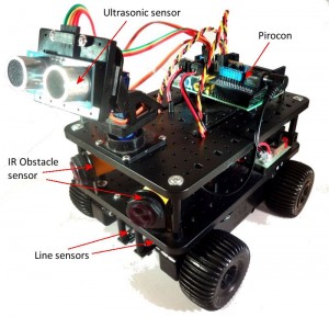
The Completed Ultimate Kit looks like this:
NB: At this point you will have 3 cables remaining:
- 2 cables with 4 wires each: Red, Black, Orange, Brown. These are the wheel sensors and it is recommended not to bother with these until you are fully familiar with the system
- 1 cables with Red & Black wires from the switch board. This is an alternative for the DC jack power cable and is not required for the PiRoCon. Other controller boards have 2-pin screw terminals which you would use this cable with. Ensure that the 2 ends of this cable to not short against each other or anything else
Connecting Wheels Sensors from Initio
The level shifters on the Pirocon are not compatible with the outputs of the wheel sensors, so you must use the wheel sensors at 3.3V and connect the output(s) directly to the GPIO pins. To do this with Pirocon:
- Remove the blue jumpers from the pin(s) you want to use from the block of 8 jumpers. Let’s use #22 and #23
- Connect the Black wire from each wheel sensor to a suitable Gnd pin – you could use the grounds for #22/x15 and #23/x16 as these are not being used otherwise
- Connect the Red wire from each wheel sensor to a 3.3V connection – there are 2 pins near the pin 25 end of the GPIO connector for this purpose
- Connect the Orange (or Brown) wire from each wheel sensor to the pins marked #22 and #23 (where the jumpers were removed)
- You can now read these two pins to get 18 pulses (36 edges) per revolution of each wheel
- If you additionally use the Brown wires from each sensor (you will need to use 2 more pins and remove 2 more jumpers) you can get additional, out of phase, readings for each wheel. This allows you to determine the direction of travel of each wheel as well as speed. When you detect an edge on one signal, then the level of the other signal will tell you which direction the Initio is going

