Initio Chassis Build

Building the Initio Chassis

step11a

As with all kits of this type, there are a variety of ways to put this together. The following steps assume you will be building one of our Arduino or Raspberry Pi kits.

1 What’s in the Box?

step01

The Initio chassis comprises the major parts:

  • Base chassis with fitted motors, gearbox, battery box, switch PCB and wheel sensors
  • Top plate
  • 4 wheels
  • 3 bags of screws (with labels)
  • Wires to connect to switch PCB depending on use
  • Wire tidies to keep your cabling neat
  • Bag of plastic pillars and brackets
  • Plastic plate to clip onto a mini-pan tilt


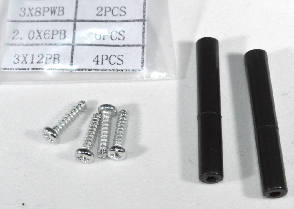
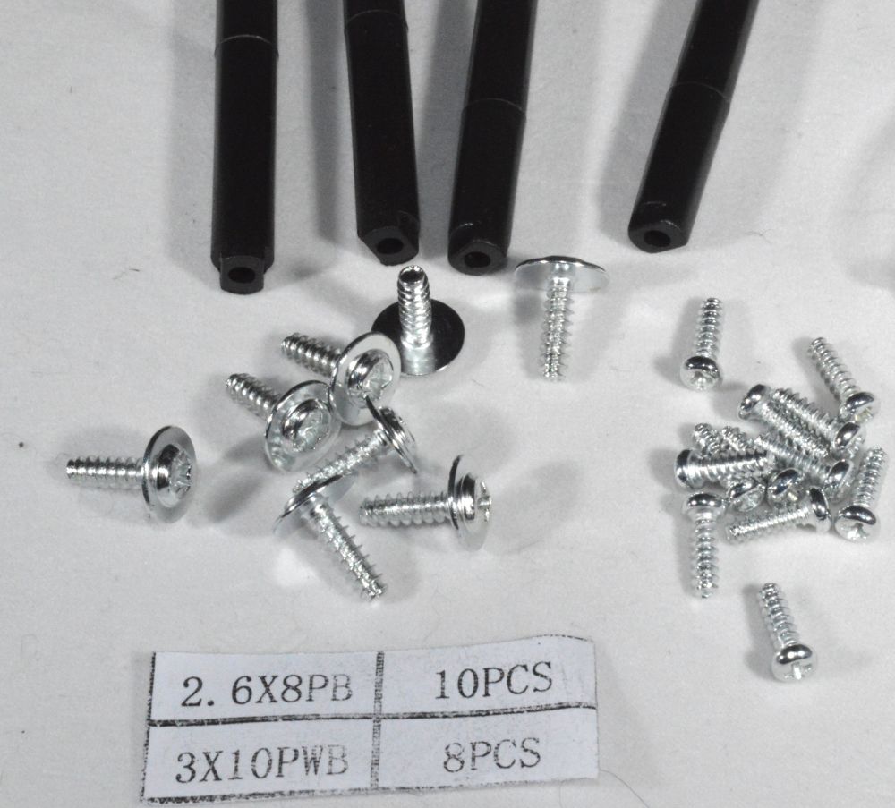
2. Which Screw is Which?

screws01b

From left to right:

  1. 36 screws for mounting the general purpose stand-offs etc. (you shouldn’t need these for the basic build, but 2 are used for mounting line followers)
  2. Three types of screws for sensors:
    1. 2 wide head screws for mounting obstacle sensor brackets (one each)
    2. 6 small screws for mounting the pan/tilt assembly (4) and mounting the saddle clamp to the pan/tilt plate (2)
    3. 4 long screws for mounting the line follower support pillars (2)
  3. Two types of screws for upper plate and controller
    1. 10 small screws for mounting the Arduino or Raspberry Pi (and L298N motor board if used)
    2. 8 wide head screws for mounting the upper plate


3. Connect Battery Cable to Switch PCB

step02

** It is very important to attach this to the correct connector as shown above  (labelled “batt”). Please double-check this before connecting batteries

On more recent units there are 2 connectors to the left of the battery connector on the switch board. They are both the same. Use one for the DC Jack and one for the bare-ended cables (if they are required for your build)


4. Fit the Line Follower Support Pillars

step03

There are six 40mm pillars in the kit. 4 of them have flattened ends and 2 of them are straight. The 4 with flattened ends are to support the upper plate, so select the 2 straight ones for this task.

step04

Use 2 long screws (3x12PB) from Bag2 and the 2 pillars

step05

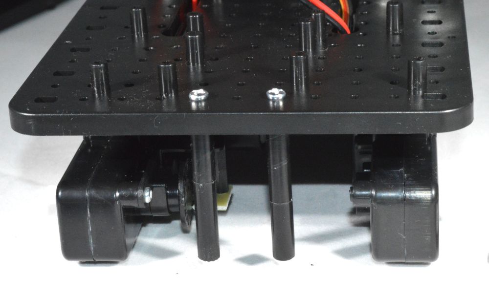
Screw the pillars in place. Note: you can vary the separation of the line following sensors by mounting the pillars in different holes, or to a lesser extent by twisting them once fitted


5. Fit the Obstacle Sensor Brackets

step06

Use the 2 wide head screws (3x8PWB) and the two plastic mounting brackets

step07

Screw the brackets in as shown above. You may want to turn them slightly away from each other so it detects obstacles off to the sides


6. Fit the Upper Mounting Plate

step08

For this we will need the 8 longer screws with wide heads (3x10PWB) and the four 40mm pillars with flattened ends

step09

Screw the 4 pillars in tightly from underneath, ensuring that the flattened ends fit snugly into the recess in the plastic plate

step10

Ensure the flattened ends at the top of each pillar fit into the recesses in the top plate, then use the remaining 4 screws to tighten the plate in position


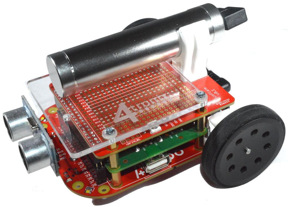
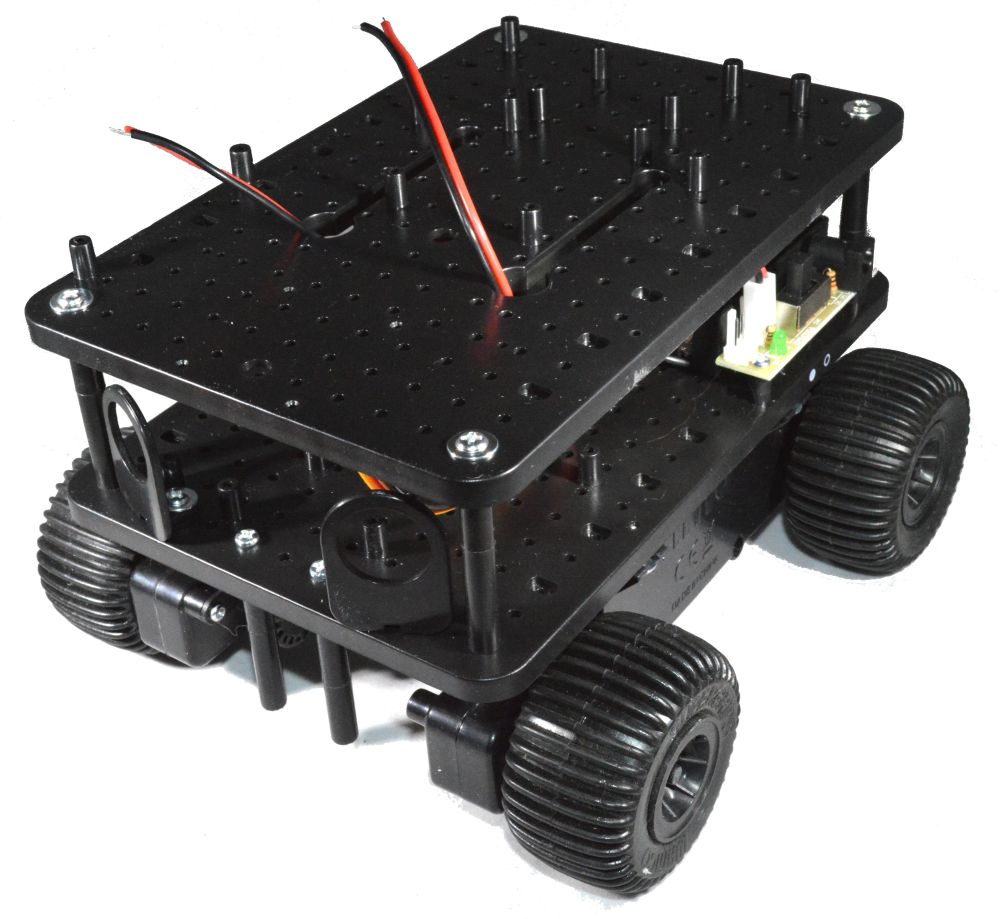
7. Chassis build is now complete

step11a


8. Fit your chosen controller

Note that there are many mounting positions that can accommodate a number of different boards from the Raspberry Pi, Arduino and other families. Depending which board is being fitted, some of the other pillars may need to be removed to avoid fouling on components underneath the boards. Simply snip off the unwanted pillars using side-cutters, nail clippers, or a sharp knife.

Some of the pillars that you are not screwing into should be left to support the board – only cut off the ones that are in the way

step12

Use the small screws (2.6x8PB)

Fitting an Arduino

step13

For the Uno, all 4 mountings can be used if desired. I generally use only 2


Fitting a Raspberry Pi Model B

step14


Fitting a Raspberry Pi Model B+

step15


Agobo Software

Software for Agobo

Python

You can download the latest python software: as a RAR file, or from GitHub

Alternatively, you can use the following commands from your Raspberry Pi in the home folder. (open LXTerminal from desktop):

  • wget http://4tronix.co.uk/agobo.sh -O agobo.sh
  • bash agobo.sh


Files included

  • agobo.py This is the python library module, see the first few lines of the library for listing of all the exposed functions for controlling motors, LEDs and reading sensors
  • motorTest2.py – use the arrow keys on your keyboard to control the direction and speed of the motors
  • irTest.py – check the state of the IR line sensors
  • sonarTest.py – print the distance using the UltraSonic sensor
  • ledTest.py – flashes the white LEDs on Agobo. NOTE: This does not operate the neopixels on Agobo2, see the note below
  • switchTest.py – shows the state of the mode switch once per second
  • neopixel.py and strandtest.py – produce pretty patterns on the neopixel attached to PlusPlate and any extended ones see Adafruit’s blog for info


Setting up Agobo2 Neopixels

Before you can use the neopixels on Agobo2, you will need to install the necessary drivers. This is the same operation as for the PlayHAT, so let’s use the instructions for that. You can always move the files over to your Agobo folder afterwards

Ensure your Raspberry Pi is connected to the internet

$ sudo apt-get install git$ git clone https://github.com/4tronix/PlayHAT
$ cd ~/PlayHAT
$ sudo apt-get install python-pip python-dev
$ sudo python setup.py install

Now you can run the strandtest.py demo as follows:
$ sudo python strandtest.py

Agobo Hackable Robot for Raspberry Pi Model A+

Specification

  • Designed for Raspberry Pi Model A+ (Can also fit B+ and 2B using optional mountings)
  • Pre-assembled. Only requires front caster, battery holder and Pi to be screwed on and then push the wheels on.
  • Raspberry Pi plugs directly onto the main PCB
  • Two N20 size metal geared motors fully and individually controllable in software
  • Built in line-follower sensors with indicator LEDs
  • Separately controllable front LEDs left and right (on Agobo2 these are fully addressable RGB neopixels)
  • Power on/off switch and LED
  • Connector for optional plug-in ultrasonic distance sensor
  • Breakout header for a standard serial console cable (ideal way to program a headless Model A+)
  • Breakout I²C header for our IP Display dongle
  • Prototyping area to add your own sensors
  • Fully replicated 40-pin GPIO header so you can attach your own addons
  • Additional mounting holes to attach sensors or extra hardware


Optional Extras

  • Ultrasonic sensors (HC-SR04) which simply plugs into the connector at the front
  • Acrylic cover with mounting hardware to cover and protect the Raspberry Pi Model A+ (included as standard in Agobo2)
  • PlusPlate™ Additional prototyping board and mounting hardware. This allows a full size area to add your own electronics from a simple LED, to more complex items including integrated circuits, RF modules and neopixels. See separate specification. The board comes complete with single, ready-wired, neoPixel with interface to extend to many, and a position for nRF24L01 socket
  • Serial console cable which allows easy access to the Raspberry Pi command line without any setup required
  • Super short micro USB cable to tidy up the battery connection
  • Pre-loaded SD card with the latest Raspbian software and Agobo software (Python and Scratch)
  • Wifi dongle
  • Additional mounting accessories to enable mounting the Raspberry Pi B+ or Raspberry Pi 2 Model B


Software

  • A Python library module and examples can be downloaded directly onto the A+ (if it has an internet connection) or transferred via USB stick or console cable
  • ScratchGPIO supports Agobo as an Addon board type from release 6.xxx (TBD)


Links


Agobo Features Walk-Through

Agobo with Ultrasonic sensor, WiFi dongle and short USB cable added to standard build

(Agobo2 has the Raspberry Pi turned 90 degrees so that fitting the B+ and 2B is possible)

Agobo – The Hackable Pre-Built Robot for the Raspberry Pi A+

Base Build

  1. Pre-Built PCB with the following items pre-installed and ready to use
  2. 2 x Metal geared Motors
    1. Left motor on physical GPIO pins 19 and 21
    2. Right motor on physical pins 24 and 26
  3. Two InfraRed IR line sensors
    1. Left on physical pin 7 with Red indicator LED
    2. Right on physical pin 11 with Green indicator LED
  4. Two White LEDs at the front (Agobo v1 only. On Agobo2 these are replaced by full addressable RGB neopixels)
    1. Left on physical pin 15
    2. Right on physical pin 13
  5. Mode switch – or whatever you want to use it for on physical GPIO pin 16
  6. Ultrasonic uses physical pin 23 for BOTH Ping and Echo. Swapping the direction of this pin is handled within the python library and ScratchGPIO
  7. I2C pins broken out to 6-pin connector with 5v, 3.3V and Ground
  8. Serial pins connected to a convenient 4-pin male connector so serial console cables plug right in (includes power and ground)
  9. Fully replicated 40-pin GPIO connector and prototyping area with 5v, Ground and 3.3V strips for you to add your own sensors, LEDs, or whatever
  10. All other pins free to do what you want


PlusPlate

  1. Lots more prototyping area
  2. Designed so ICs can fit in 4 different rows with easy access to 5V, Ground and 3V distribution lines
  3. A great way of adding any sort of electronics
  4. Use the Acrylic cover to safely protect your designs
  5. Physical GPIO pin 12 is brought to a pre-fitted neopixel which is directly controllable in python (and ScratchGPOIO??)
  6. Both the input and the output to the neopixel is brought to an expansion header so your pre-fitted pxiel can be in parallel with or in addition to the first pixel in your strip or ring of pixels
  7. All unassigned GPIO pins (as well as 5V, 3.3V and Ground) brought to a separate row of accessible pads
  8. A position for a standard nRF24L01+ module using SPI connections
  9. With the PlusPlate™, the Agobo becomes infinitely hackable!


Assembling the Agobo Robot for Raspberry Pi A+

 Click on any image below to enlarge

*Note. Images still show the Agobo v1 build. Agobo2 is similar but rotated 90 degrees.

Basic Build

1. Check you have all the parts:

  • Agobo ready built main board
  • 2 rear wheels
  • Front caster bag containing read-assembled caster
  • Acrylic cover with “Agobo2” etched on
  • Battery holder clip
  • 16mm countersunk screw
  • M3 nut
  • 4 x 11 mm female-female pillars
  • 8 x 6mm screws
  • Battery with connector/charge cable
  • 4 male-female pillars (5mm)
  • 4 nylon washers


2. Fit the Front Caster

For Agobo2 this has already been done for you, so skip to Step 3

This is a fiddly task, but it is the only one. Once it is done, the rest is easy

agb10_02

Put the main ball in the housing, and the small balls into the “corners” as shown above


agb10_03

Put on the cover plate and hold it all together with your fingers, as you place it on the PCB


agb10_04

Then use the small (10mm) screws to fix it to the PCB.

That wasn’t so hard, right? (NB. If using the PlusPlate™, or wiring onto the replicated header pads, you will need to use the 3mm spacers and the longer screws – this is a much trickier operation)


3. Fit the Battery Holder

For Agobo2, the battery holder is fitted to the Acrylic plate, so skip to step 4

agb10_05

You will need the 5mm small acrylic plate, 20mm countersunk screw, M3 nut and the battery clip


agb10_06

Remove the backing plastic from the acrylic plate – it should be bright and transparent

Push the screw through from the top of the battery clip, through the acrylic plate, through the PCB and tighten the M3 nut underneath


4. Add the Mounting Pillars for the Pi

agb10_07

You will need the 4 female-female pillars (11mm) and the 8 screws (M2.5, 6mm)


agb10_08

Screw the 4 pillars into the PCB in the positions shown


5. Fitting the Acrylic Plate

agb10_12


6. Add the pillars

agb10_13

Screw the 5mm male-female pillars in to the 11mm pillars that hold the Raspberry Pi A+


3. Fit the Acrylic Cover

agb10_15

  • Peel off the protective covering from the acrylic plate (now it is nice and shiny!)
  • Screw the battery clip to the offset hole in the acrylic using the 16mm screws and M3 nut (the 5mm spacer acrylic piece is not required)
  • Now use the 6mm screws with the nylon washers to hold the acrylic cover to the small pillars
  • All done!


—–

Using with the PlusPlate

1. Check you have all the parts

agb10_16

To attach the PlusPlate you will have to do some light soldering.

First, fit the 2x20pin male headers to the main board as shown above


2. Re-Attach the Front Caster with spacers

agb10_17

Note: This is really tricky – take it carefully and patiently. There is a knack to doing it, which is described below, but it takes a few attempts before you can do it quickly.

You will need the longer screws and the 3mm spacers found in the bag with the front caster.

  • Prepare the front caster as before and hold in one hand
  • Hold the main PCB vertical (ie. resting on the back end (USB connector end)
  • Put one long screw through the hole in the PCB
  • Put a spacer over the screw so that it rests on it – remember, the screw is horizontal at this point. Gravity is your friend.
  • Screw into the caster assembly with the other hole of the caster upwards(careful, though as it is easy to over-tighten)
  • Now turn the caster into the correct position, and push the other spacer into position
  • Then, screw the second screw in.
  • Now, you can have a cup of coffee, or glass of wine, or whatever. You deserve it!


3. Add the Mounting Pillars

agb10_18

Use the 4 Male-Female 11mm pillars and screw each on in, holding the Pi in place


4. Prepare the PlusPlate

agb10_19

Solder the 40-way female header to the bottom of the PlusPlate

agb10_20

Push in the 40-way extended header

agb10_21


5. Connect the PlusPlate and Battery

agb10_22

Push the PlusPlate with extended headers into the male headers that you soldered onto the main PCB


agb10_23

Fix the PlusPlate with the 6mm screws (from the base build)

Add the battery clip to the PlusPlate using the 12mm countersunk screw


agb10_24a

Fit the battery and off you go!


You can also add the Acrylic cover with the PlusPlate

agb10_25a

Use the 5mm Male-Female pillars and mount the acrylic cover with the overhang at the front

Leave the battery clip fitted to the PlusPlate to reduce the overall height.

Picobot: Low-Cost, Feature-Rich Arduino-Compatible Robot

Picobot – Low-Cost Open-Source Robot for Education and Fun!

pb1_02a

For little more than the cost of an Arduino Uno, you can buy a compatible product that works directly with the Arduino IDE and has built in motors, sensors and LEDs. You can add to this with plug-in modules for ultrasonic distance measurement and 2.4GHz wireless connectivity

Buy it here

Dimensions:
PCB 50 x 50mm
With wheels, width is 80mm
Including ultrasonic and rear LED, length is 75mm
Height without ultrasonic is diameter of wheels (42mm)
Height with Ultrasonic is 48mm

The circuit schematic and example code is Open Source and available for anyone to make their own. Licensed under Creative Commons BY-SA
The design files and basic program examples are on the 4tronix GitHub
The library and 3D printable case are from Martin Bateman

Also available as a Starter Pack with 2 Picobots, programming cable and batteries

Save even more by purchasing a Class Pack of 6 or more

Some example activities:
Without RF Connectivity:

  • Line following
  • Obstacle avoidance
  • Light seeking
  • Light avoiding
  • Colour reaction to environment Light vs Distance, Colour vs Light received, etc
  • Follow my leader (pulse the rear LED and get second Picobot to follow a pulsing white light)
  • Stay fixed distance from object/person – eg. get it to follow you around

With RF Connectivity:

  • Synchronise colours
  • Dance in sync
  • All follow the command of a leader
  • Send commands or data from a Raspberry Pi or PC
  • Classic swarming behaviour: react to alarms, searching, clustering, identifying

Video of Picobots preparing to follow each other

Base Model Comprises:

  • Ready assembled – just push on the wheels and screw in the front caster assembly
  • Arduino compatible ATMega328P-AU (with 2 additional analog inputs)
  • 2 x N20 geared motors with “biscuit” 42mm diameter wheels
  • 2 forward facing light sensors
  • 2 line sensors
  • 2 paired RGB LEDs underneath for mood lighting and status information depending how you want to program them – they both show the same colour, not independent
  • Rear facing bright white LED – useful for “follow my leader”
  • Mode selection button – general purpose input button that you can program yourself
  • On – Off switch
  • Reset button
  • Socket for ultrasonic distance sensor HC-SR04
  • Socket of 2.4GHz RF module – nRF24L01 or compatible
  • Socket for programming (requires a USB to serial converter such as a CP2102 module with DTR, must be pin for pin compatible with the one 4tronix sell)
  • NB. Basic model does not include battery or battery holder as you can use any LiPo or LiOn battery or battery holder with 2-pin JST plug (check the polarity)

Available Upgrades and Options:

  • Ultrasonic distance sensor HC-SR04
  • Programming module and USB cable (CP2102 USB to Serial converter)
  • 2.4GHz transceiver nRF24L01 or compatible (NB. this is not Bluetooth and a similar transceiver is required to connect to other devices)
  • 3-Cell AA battery holder
  • Lithium Ion battery (similar to PS3 controller batteries, but polarity is reversed)
  • Lithium polymer battery (various capacities)

Gallery