“QUARK” – Overview and Description
(Click any image to enlarge)
Now updated to include V0.2

Version 0.2 “Button”, “Blinkies” and underside of “Proto”

v0.1 Top side
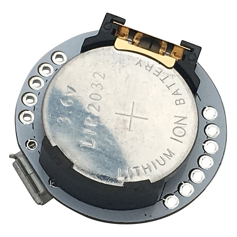
v0.1 under side
Specification
- Processor: ATMega328P-AU
- Clock Speed 16MHz
- Fully compatible with Arduino Uno
- USB Interface: CH340G
- Battery: Rechargeable Lithium Ion LIR2032 (3.6V nominal)
- Diameter: 28mm (v0.1 was 27.25mm)
- Weight: 2.9g without battery (5.5g with battery)
- On-board Charger, with charge indication LEDs
- On-Off Switch
- D13 LED (Blue)
- 4 Digital I/O Pins (Arduino Uno pins D2, D3, D4, D5)
- 4 Analog I/O Pins (Arduino Uno pins A0, A1, A4, A5)
- I2C pins (Shared with pins A4 and A5)
Changes between v0.1 and v0.2
The only real change is the header strips which are now both 6-pin straight headers instead of one 5-pin and one 7-pin curved. This allows us to actually fit headers and I have fitted 6-pin low-profile female headers
I’ve blocked off one pin to act as a polarising location, so plugin boards will only fit one way – having cut off the matching pin on the plugin’s male header. (Note. this polarising scheme will change in the next revision and existing plugins will not be compatible)
We’ve also shipped these with 2 additional plugins:
- Blinkies – a set of WS2812B-compatible smart pixels (aka neopixels). These are connected to pin D4 on the “Arduino” and can be driven using the FastLed library
- Proto – a simple prototype board allowing you to add sensors: digital, analog or I2C of your choice
- 56 holes arranged in 7 rows of 8
- The middle 4 pins of top row are connected to A5, A4, A1, A0 respectively (note that A4 and A5 are the default I2C pins SDA and SCL)
- The middle 4 pins of the bottom row are connected to D5, D4, D3, D2
- Additional 5 Ground pins on the left
- Additional 5 Vcc pins on the right
Getting Started
- You will need the Arduino IDE – download from the Arduino website
- You may also need drivers for the CH340 USB interface. These are included with Windows 10, but also available online (just Google for your OS and CH341 or CH340)
- You’ll also need a Micro USB lead
- Set up the IDE with the correct COM Port, and use board type Arduino/Genuino UNO
- The boards have been shipped running the Example Blink sketch and so will blink the Blue LED on and off every second
Charging
- The built-in LIR2032 battery will last around an hour or so, depending what it is doing (based on the same circuit running on the 4tronix SmartBadge which lasts 45 minutes when powering neopixels)
- It will take about 30 to 40 minutes to charge if switched off
- The Red LED indicates charging and faster charging will occur if the unit is switched off during the charging
- The charge is complete, the Green LED is lit and the charging circuit shuts down
- Whenever the USB lead is plugged in, it will charge, but this is only really effective when the Quark is switched off
Know Your “Quark”

v0.2 Pinout

V0.1 Pinout
Naming
- There is a project on my system named Quark, which has several designs in a partially complete stage. This is just the first one onto a PCB.
- Intel already have a product range Quark, so we won’t be using this name when/if the product gets released.
- Please let me know of any name ideas you think may fly


