The 4tronix dew heater controller is available in both 2-channel and 4-channel versions. Apart from the number of channels, they are identical in operation – in fact they use the same PCB and the same code on the internal microcontroller.
Each channel is fully variable from completely Off to permanently On. The positions in between are managed using PWM (Pulse Width Modulation), which is a method of reducing the overall power usage, while keeping the voltage level the same. Basically, it provides power at the input voltage for a certain percentage of the time, with the power off for the rest of the time during each period. Each PWM period is only about 2ms, so you won’t see any fluctuating values.
There is an indicator LED on each channel to give some indication of the power selected. If the indicator LED is Off, then there is no power being provided to the dew heater. If it is On solidly, then the full input voltage is being provided to the heater. In between, the LED flashes. A slow flash indicates little power and a fast flash (up to 30 Hz) indicates more power. Note that the flashing of the LED is not the same as the PWM values on the heater outputs.
The Dew Heater Controller can operate happily from about 7V up to about 15V. The driver for each channel is rated at over 4A, but do not use all 4 channels at 4A – other parts of the circuit won’t cope.
The power is supplied via a 5.5mm DC Jack, with centre Positive. There is a reverse polarity protection circuit inside, just in case you get it wrong.
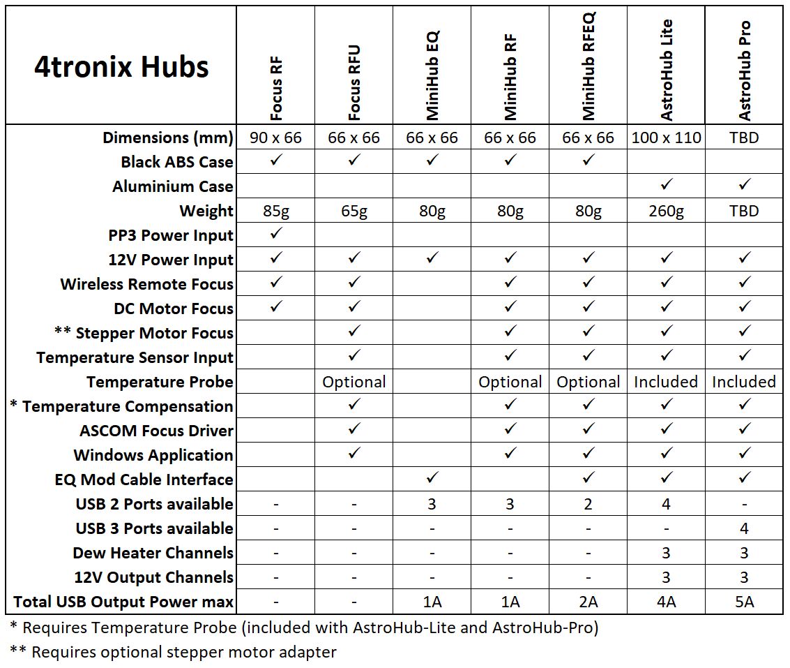
Note: See the AstroHub blog page for information about the Focus RFU as the method of using the remote is different and for information on using the Windows application. There are more products available in our AstroHub and MiniHub ranges as shown here
Overview
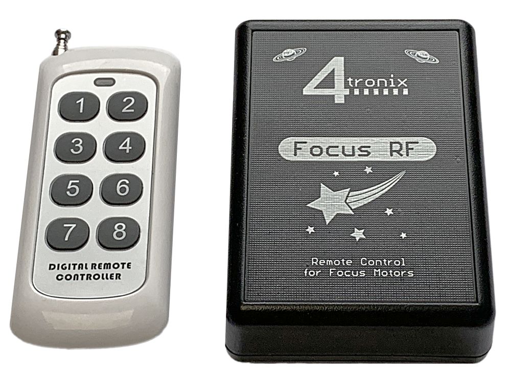
The 4tronix Focus RF system replaces the manual handset in the Skywatcher compatible auto-focuser kit. It provides a simple wireless interface to control the motor at 4 different speeds with the fastest speed determined by the power supply used and the slowest speed being configurable.
The left buttons (1, 3, 5, 7) turn the motor one way and the right buttons (2, 4, 6, 8) turn the motor the other way. Buttons 1 and 2 are slowest, buttons 7 and 8 are fastest.
You can add, delete or replace remotes (requires the case to be opened)
Normal Operation
You can power the FocusRF from a 9V PP3 battery which can be fitted inside the case, or you can use an external 9V to 13V power supply with a 2.1mm DC Jack, centre positive.
Clip the end of the cable from the motor into the RJ22 in the FocusRF, instead of into the handset. All is now ready to go.
When the switch is moved to ON, the Red LED will initially come on solidly for a few seconds, then begin to flash slowly.
Press any of the buttons on the remote (which has already been paired to your FocusRF before shipping) and the green LED on the FocusRF will come on and go off again when you release the button. The focus motor will turn while you hold the button, then stop when you release it.
Speed Configuration
(Focus RF only) The default slowest speed may be too slow for your setup: the battery may not have the power to turn the motor, or the motor is too stiff to move for instance. Alternatively, you may want an even slower speed – especially if you are using an external power supply of more than 9V.
During the few seconds after switch on, when the Red LED is on solidly, press button 7, then 8 on the remote. This enters speed configuration mode.
Then press any of the buttons 1 to 8 to set the minimum speed. The default setting is 5. After pressing the selected speed, FocusRF will store the new minimum speed even during power down, removal of battery etc.
Pressing any button other than 7 then 8 at the start, will immediately move to normal operation and start moving the motor at the speed given.
Configuring RF Remotes
The 433MHz RF interface to the remote control is handled by a small daughter board inside the FocusRF unit. Using the button and the LED on the daughter board, you can add new remotes, delete all remotes and set configuration mode.
There are four screws on the bottom of the FocusRF case which you need to unscrew to get at the daughter board. You do not need to remove the internal PCB or the daughter board.
Add New Remote
Switch on the FocusRF
Press the button on the daughter board briefly – the Green LED on daughter board will light solidly
Press each button on the remote in turn, from 1 to 8. The Green LED will briefly turn off to acknowledge each button press.
When all 8 buttons have been pressed, press the button on the daughter board briefly again – the Green LED will turn off and the new remote is now stored
Delete All Remotes
For remotes since November 2021:
Switch on the Focus RF
Press the button on the daughter board three times in quick succession
The Green LED will flash quickly for a few seconds while it clears the memory
When the Green LED goes out, switch off the Focus RF
All stored remotes are now cleared
For remotes prior to November 2021: Note that this function also clears the configuration mode, so you will also have to reset this (next section)
Switch on the FocusRF
Press and hold the button on the daughter board
After a second or so, the Green LED will flash once (keep pressing the button)
The Green LED will then flash twice, then 3 times, 4 times, 5 times and 6 times
After it has flashed 6 times, release the button
The unit has now been reset and has forgotten all remotes and all configuration settings.
Set RF Configuration Mode
The RF module is capable of several operation modes. FocusRF uses Mode 1 or Mode 2 depending on the wireless receiver model that has been fitted. All other modes will result in unreliable operation. The following operation sets Mode 2, all units shipped after November 2021 use Mode 1 so stop after step 3 and release the button.
Switch on the FocusRF
Press and hold the button on the daughter board
After a second or so, the Green LED will flash once (keep pressing the button)
After another second, the Green LED will flash twice