Assembling and Using Robobit Mk3

Robobit Mk3 buggy is a fully integrated and updated version of the Mk2 with all options (except Talon grabber) ready integrated into the unit
Purchase Robobit Mk3 here
Features
- Compact design DIY robot that is easy and quick to build
- No soldering required. Screwdriver and spanner widget included and are the only tools required
- Presented in an attractive gift box
- Integrated ultrasonic distance sensor
- Integrated line follower sensors
- Integrated pen holder (designed for Sharpies, but other pens will fit)
- Integrated RGB smart LEDs (aka neopixels) with semi-automatic Larsson scanner function
- Fully supported by the Microsoft Makecode extension – search extensions for “Robobit”
- Powered by 4 x AA batteries (not included)
Assembly
Step 1 – Check you Have the Correct Parts

- Main PCBA with prefitted ultrasonic sensor
- Battery Holder PCBA (NB. Ring fits to rear of robot – no matter what it says on it!)
- 2 x bags with motor mountings
- Bag with 4 x 6mm M2.5 screws and 2 x 25mm pillars (6 screws on v1.2 and earlier)
- 2 x motors with pre-fitted cables and plugs
- 2 x Wheels
You should also have 2 tools: a double ended screwdriver (pull out of handle and turn round ot get alternate end), and a Pimoroni “spanner widget” for the motor mount nuts
Step 2 – Fit the motor brackets to the Motors

Mount the brackets the opposite way to each other so you have left hand and right hand assmblies as shown.
Use the Pimoroni spanner widget to held the nuts while you tighten the screws.
NB. Very important to ensure the edges of the nuts are flat with the top of the motors or the motors will be at a strange angle when fitted.
Step 3 – Fit Motors to Mainboard

Use the two 8mm M3 screws in each motor mount bag to fit the motors to the top of the main PCBA as shown above. Do these up tightly so the motors do not come loose with use.
Ensure the axles are at the rear and facing outwards.
Tighten the screws fully
Step 4 – Fit the Front Caster (v1.2 and earlier only)
Remove the ball if it is supplied already in the housing
Use two of the 6mm screws to fit the housing the the bottom of the main board as shown above
Step 5 – Fit the Battery Mounting Pillars

Use two of the 6mm screws to fit the 25mm pillars as shown above
Tighten up fully
Step 6 – Attach the Battery Holder

Use the remaining two 6mm screws to attach the battery holder firmly
Ensure the pen holder ring of the battery holder is directly above the pen holder hole in the main board
Step 7 – Finish
Push on the wheels and pop in the caster ball
Fit batteries.
Add your Micro:Bit and start programming!
Visit Programming Robobit Buggy in Makecode
Programming in Python
For text-based programming there is micro-python, and I prefer to use this offline using the Mu editor. It provides a very neat and easy way of interfacing to the micro:bit without all the fuss of dragging and dropping.
Note on examples: We want to show people how the various features can be used. We don’t want to do the coding for you – that is the learning experience you should be taking away from using it. In the following examples, we will give you the tools to use all the features of Bit:Bot but it is up to you to combine them together in your code to make it do something useful. We do give a complete example of line-following – but it is a very basic algorithm and will get confused at T-junctions and crossings; and it doesn’t use the neopixels.
Some great tutorials/examples for BitBot (which is very similar) by Mark Atkinson here
Motors
Each motor has two pins connected to it. One determines the speed and the other the direction:
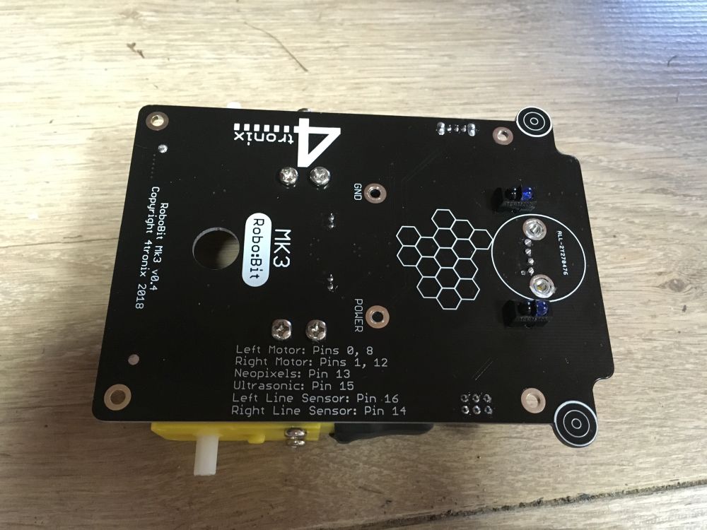
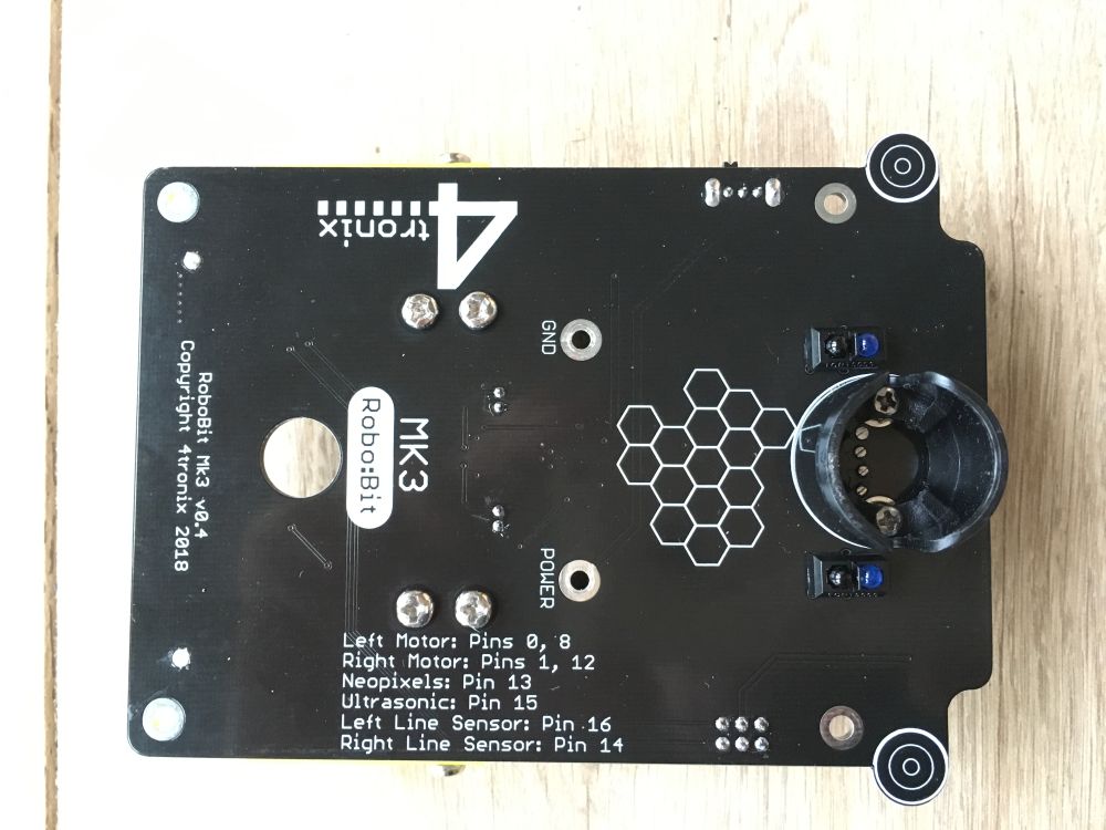
Left motor: Speed Pin 0, Direction, Pin 8
Right motor: Speed Pin 1, Direction Pin 12
The simplest way to make the motors move is to set the Speed pin to HIGH and the Direction pin to LOW (to move full speed forwards)
Move left motor Forwards:
pin0.write_digital(1)
pin8.write_digital(0)
Move left motor Reverse:
pin0.write_digital(0)
pin8.write_digital(1)
If we want to change the speed of a motor, so that it is not going at full speed all the time, we need to use PWM (Pulse Width Modulation). This is means of changing the amount of power given to the motor by switching it on and off very fast. The percentage value of PWM determines the amount of each cycle that the output is ON. So a percentage of 100% is the same as being on all the time and thus the same as the examples above. A percentage of 50% would mean that the motor is only energised half the time, so it will go much slower. Note that the actual speed of the motor is not the same as the percentage of PWM – the motor won’t turn at all if the PWM value is too low and you will also get some stuttering at certain values. Nevertheless, being able to change the speed makes for a much better robot. For example, you can make a line follower that smoothly follows the line, rather than the normal shaking left and right.
To change the PWM value of a pin, we must use the analog_write commands. These can be set to a value between 0 (always off) to 1023 (always on), so 50% would be 511. Here are the commands to change the speed of the Right motor to approx 75% (value is 770)
Move right motor forwards at 75%
pin1.write_analog(770)
pin12.write_digital(0)
Doing this for the motors moving in reverse is a little confusing. Remember we need to change the direction pin to 1 for reverse. Then we need to set the amount of time in each cycle that the speed pin is LOW. This is the opposite of moving forwards, where we set the time for it to be High. Se we simply take the number (770 in this case) away from 1023, giving 253:
Move right motor Reverse at 75%
pin1.write_analog(253)
pin12.write_digital(1)
Neopixels
In fact, the name “neopixel” is a termed coined by Adafruit, but like “hoover” was a name of a brand of vacuum cleaner and is now a general term for all similar products, whoever makes it. The generic term is “smart RGB pixel” and is usually referenced with the name of the chip WS2812B. However, there are many different chips, all performing in a compatible way. The ones on the Robobit Buggy Mk3 are actually SK6812-3535
These smart RGB pixels are able to display any of 16 million colours by selecting a value of 0 to 255 for each of the Red, Green and Blue LEDs on each chip. The whole thing is controlled by a single pin on the BBC micro:bit (pin 13 for Robobit Buggy Mk3). It is simple to use the included neopixel libraries to control each pixel individually.
The 8 pixels are labelled on the Robobit Buggy Mk3, from 0 on the left arm to 7 on the right.
Set neopixel 2 to purple (red and blue)
import neopixel
np = neopixel.NeoPixel(pin13, 12)
np[2] = (40, 0, 40)
np.show( )
The first line imports the neopixel library. We only need to do this once, at the very top of your Python programThe second line creates an Python list with an element for each pixel. As shown, it specifies 12 pixels connected to pin 13. If you added more neopixels then you would increase the number from 12 by the number of pixels you added. eg. if you added a McRoboFace, then the total would be 12 + 17 = 29 so you would change the line to: np = neopixel.NeoPixel(pin13, 29)
The third line sets the pixel we have selected (number 2 in this case) to the colour which is set by three values in the brackets, each value can be from 0 to 255 and covers Red, Green and Blue. In our example we have set Red and Blue to 40.
The fourth line tells the neopixel library to copy all the data to the neopixels, from the Python list that we have been working with. It is only at this point that the LEDs change. In general, you would make all the changes you want and only at the end would you use a np.show( )
Line Follower Sensors
These are digital inputs and connected to Pin 16 (left) and Pin 14 (right).
You can use digital_read commands (as shown below) to read the value of each sensor. If the left sensor detects a line, it means the Robobit Buggy Mk3 is too far to the right, so it should move left. The opposite is the case if the right sensor detects a line. Here is some simple code for line following in Python (the actual motor commands are in separate functions for clarity)
while True:
lline = pin16.read_digital()
rline = pin14.read_digital()
if (lline == 1):
spinLeft( )
elif (rline == 1):
spinRight( )
else:
forward(speed)
Ultrasonic Distance Sensor
The integrated HC-SR04P ultrasonic distance sensor addon can be used most easily in Microsoft PXT. In MicroPython we can use the utime module to measure time at microsecond level. Below we have a function called getDistance() which returns the number of cm to the nearest object. Then we have a while loop that prints the distance every second:
def getDistance():
pin15.write_digital(1) # Send 10us Ping pulse
sleep_us(10)
pin15.write_digital(0)
while pin15.read_digital() == 0: # ensure Ping pulse has cleared
pass
start = ticks_us() # define starting time
while SONAR.read_digital() == 1: # wait for Echo pulse to return
pass
end = ticks_us() # define ending time
echo = end-start
distance = int(0.01715 * echo) # Calculate cm distance
return distance
while True:
display.scroll (getDistance ( ) )
sleep(1000)