Programming Robobit Buggy
The Microbit Makecode Package supports all versions of the Robobit. Go to https://makecode.microbit.org/ or download the PC app from here
Select Advanced or click on the gear icon, then select Extensions. Enter Robobit in the search box and search.

After it has loaded you will have an extra tool in 4tronix Orange with the Taxi icon, called Robobit

If you click on the Robobit tool, there are 3 subfolders for the Motors, the Sensors and the LedBar. There is also a single top-level block to allow you to select your model of Robobit – this should be used at the very start as shown below. In fact it can be the only thing in the start block

Now you are ready to start programming…
Programming the Motors
It’s a robot – you want it to move. So let’s see what we need to do.
The motors are individually controllable. So if you want, you can set different speeds for the left and right motors. But to start simply, let’s just drive forwards and backwards.
Forwards is represented by speeds from 0 to 1023. Backwards is speeds from -1023 to 0.
In both cases, 1023 is the fastest and 0 is dead stop. You will find that speeds below 200-300 may not be able to move the robot very much (it depends on battery levels, how “free” the motors are, etc)
The following code simple drives forwards at speed 600 (both motors at the same speed) for 1 second, stops for a second, then reverses and stops again. It repeats this forever

Yes, we have a moving robot!
NB. You may find, especially when the motors are new, that they go at different speeds and it doesn’t travel in straight lines. This is normal. The motors have a 10% speed tolerance, so can always be different speeds, but when they are new they can be especially stiff and even more different. Run the motors at full spoeed for a few minutes to free them up.
More Complex Motor Control
We can try and move in a square, or other shape. Great if you’re on a piece of paper and using the pen (Pen holders are designed for Sharpie felt tip pens – other pens are available)
Drive forwards for a bit, turn for a bit and do this 4 times. If you get the speed and times correct then a square can be formed. You will have to experiment with the speeds and times
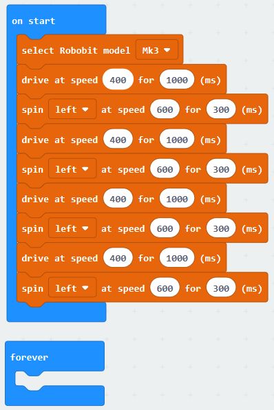
The code above (click to enlarge) will do a four-sided figure and then stop. You will have to adjust the timings and/or speed of the spin to get it to accurately draw a square.
Of course, this software is tedious. It does the same thing 4 times. It would be better to use a loop function like this:
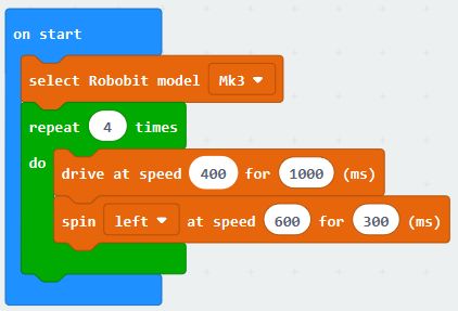
Here, we are using the “repeat nn times” block from the “Loops” toolbox
Now Let’s Flash some LEDs
It’s always fun to light LEDs and especially fun if you can control them individually with different brightness and colours.
The Robobit Mk3 and the Mk2 with LedBar have a row of 6 LEDs across the front as well as one in each front corner for a total of 8.
Scanner Feature
The Makecode package has a unique “Larsson Scanner” feature built-in which enables you to very easily scan the centre 6 LEDs back and forth at your choice speed and colour. Let’s do this to start with:
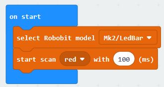
From the LedBar section of Robobit, select the “start scan…” block and insert it into the program after setting the required Robobit model. Here we are using a Mk2 Robobit with a LedBar attachment.
This code will immediately start the centre 6 LEDs scanning using various intensities of Red, with a delay of 100ms between changes, just like the Knight Rider KITT car!
Standard LED Programming
Normally when using the LEDs you will set on or more LEDs to a particular colour depending what you want the program to display. To do this, you need to understand how to work with individualy LEDs.
There are blocks you can use to set individual LEDs (or pixels), or all the LEDs at the same time. You can select colours using the names of colours (eg. Red, Yellow, Green, etc) or you can specify your own colour in terms of Red, Green and Blue components. All these blocks set the memory in the Microbit for the LEDs, but they do NOT update the LEDs with this memory information. To do that, you must use the most important block of all:

After doing this, all the changes you have made will be shown on the LEDs.
The other thing to remember is that the 8 LEDs are numbered from the left at 0 to the right at 7. So to flash the leftmost LED in Orange, we could do this:
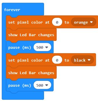
This will set the LED at position 0 to orange, then wait for half a second, then set the LED to black (this is the same as OFF), then wait another half a second. Then this keeps repeating forever. Notice that each time we update the LED information, we than “show the LedBar changes”.
Using Sensors
Depending on your Robobit model and options fitted you may have an Ultrasonic Distance sensor and/or line following sensors. For the Robobit Mk3, these are both included as standard. For the Mk2, they can be purchased as options.
The Robobit Makecode extension includes blocks for using these easily.
Line Following Sensors
There are 2 of these mounted underneath the buggy, close to the front caster. They both use the same hardware sensor (TCRT5000) but the integrated ones on the Mk3 use 4tronix electronics specifically designed for this application whereas the Mk2 uses generic modules which have a trimmer on. Turn this until the LED turns off when it goes over a black line. You will find that the integrated units perform better.
The key thing to remember is that the Robobit buggy and the motors have a lot of interia when moving and cannot stop very quickly, so you must design your line follower program to move slowly (there are clever things that can be done, but we won’t look at that now). The Mk2 will have to go slower than the Mk3 because of the difference in sensitivity of the sensors.
To create a track to follow, you can use black electrical tape, or a permanent black marker. The surface needs to be reflective and the tape or marker pen needs to be not reflective. I prefer to print the tracks using track tiles from RobotSquare as these work excellently.
The simplest algorithm will be to check each sensor. If it is over a line, then turn the buggy that way, otherwise carry straight on. Keep checking in a loop like this:
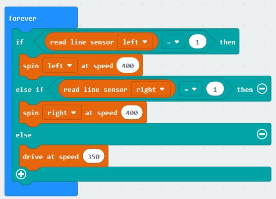
Note that we are using speeds of less than 400. For a Mk1 or Mk2 you will probably have to go even slower.
This is a very basic algorithm and will have problems with junctions on the track etc. it also won’t do very well in a speed trial.
Ultrasonic Distance Sensor
These little sensors work like bats, by sending out an ultrasound ping and waiting for the echo to come back. The time for the echo to come back, together with the speed of sound, gives us an idea of the distance. Do not expect ultimate accuracy from these sensors.
You can choose to get the distance back in different units: centimetres, inches or microseconds. These examples all use centimetres (cm).
Obstacle Avoider
This simple program drives forwards until it detects an obstacle, then spins and reverse to avoid it before setting off again.
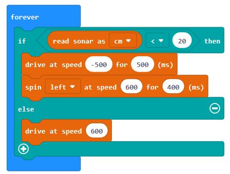
The first block checks if the robot is within 20cm of an object. If it is then it reverses at speed 500 for half a second, before turning left for 400ms. If it is not less than 20cm from an object it just drives straight on at speed 600.
Follow Me Program
This fun little program drives forwards until it gets close to an object and then stops. Then if the object (eg. your leg) gets further away, it will start moving again to follow you. However, if your leg gets closer then it will back away trying to keep the same distance from you:
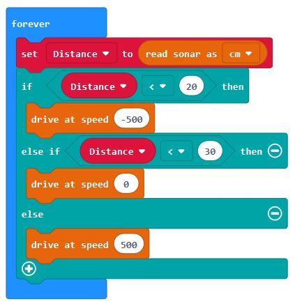
In this one, we have created a variable called Distance so that we can check it against 2 values without reading the sensor again. Here we reverse the robot if it less than 20cm away and go forwards if it is more than 30cm away. Between 20cm and 30cm the robot will stay still.