PiBug

Click on any image to enlarge
A barebones, but sturdy, 2WD buggy for the Raspberry Pi, that uses the Pi itself as the chassis for the robot.
Assembling the PiBug
Step 0 – Check you have all the parts
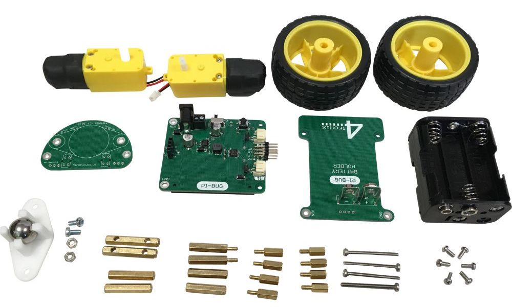
- Main board
- Caster board
- Battery board
- Battery holder
- Castor Pack containing:
- Castor ball and housing
- Screws: M3, 6mm X 2
- Nuts: M3 X 2
- Fixings Pack containing:
- 22mm F-F pillars X 2
- 22mm M-F pillars X 2
- 30mm Pillars with holes X 2
- 25mm F-F pillars X 2
- 9mm M-F pillars X 8
- 6mm M2.5 screws X 6 (2 for the caster board)
- 30mm M2.5 screws X 4
- Motors X 2
- Wheels X 2
Step 1 – Attach the Castor to the Castor board

Put the M3 nuts in the holes in the castor housing, then use the 6mm M3 screws to fit the housing tightly to the castor board as shown, with the castor on the bottom and the large 4tronix logo on the top.
Step 2 – Assemble the Motor Mounts


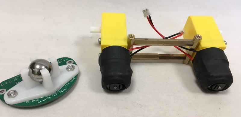
- Screw a 22mm Male-Female pillar into a 22mm Female-Female pillar tightly, making a 44mm female-female spacer (remember: 22mm is not the same as 25mm)
- Repeat to create a second 44mm spacer
- Thread the 30mm screws through the holes in the motor and through the holes in the side of the 30mm pillars, then screw into the 44mm spacers
- Important: The 30mm pillars with holes have one end rounded for about 1mm. This is the bottom, the other end is the top that fits to the Raspberry Pi. The rounded end is tapped for M3, and the hex end is tapped for M2.5. Ensure you have these the correct way up
- Ensure that the motors shafts are facing outwards as shown in the photo
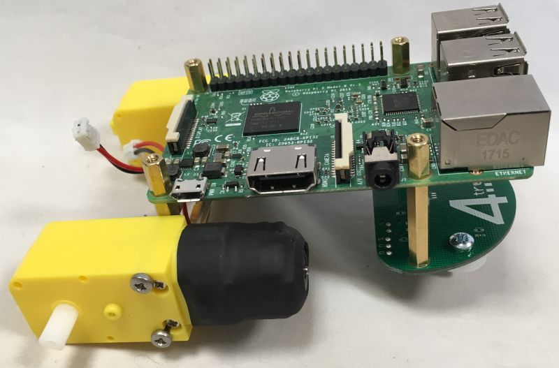
Step 3 – Fit Motor mounts to Raspberry Pi
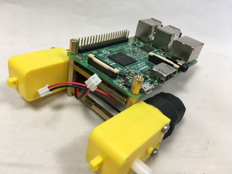
You can use either Model A or Model B varieties of Pi. You can’t use a Zero (at least not without some ingenuity…)
- In this step we will use 4 of the 9mm pillars
- Screw the threaded end of the 9mm pillars through the 2 holes in the SD card end of the Raspberry Pi and into the top of the 30mm pillars of the motor mount assembly
- Ensure all screws are tightly fastened
Step 4 – Fit the Castor assembly to Raspberry Pi
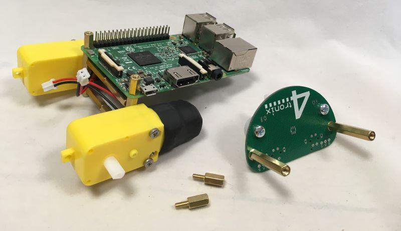
- Use 2 of the 6mm M2.5 screws to attach the 25mm pillars to the top of the castor board
- Use the 2 more of the 9mm pillars and screw through the holes in the Pi into the top of the 25mm pillars as shown
Step 5 – Fit the PiBug Main Board

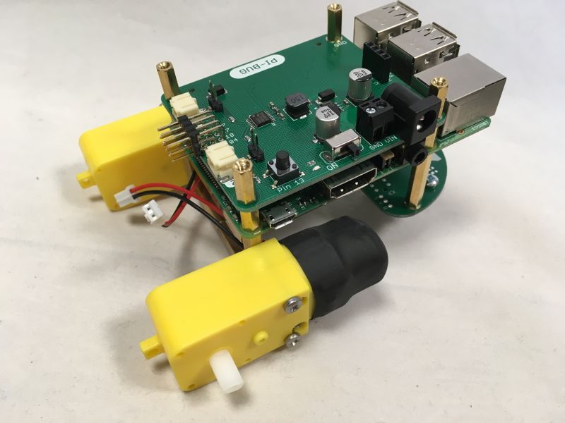
- Push the PiBug main board onto the GPIO connector of the Pi. Ensure all the pins are lined up properly and that the holes on the PiBug board line up with the 9mm pillars
- Use the threaded ends of the 4 remaining 9mm male-female pillars to fit the PiBug main board into position.
Step 6 – Fit the Battery Holder Board

Use the 4 remaining 6mm, M2.5 screws to fit the battery holder PCB as shown, with the snap connectors at the USB/ethernet end of the Raspberry Pi
Step 7 – Connecting it up

- Connect the JST leads from the motors into the appropriate motor connector on the PiBug board
- Fit 6 AA rechargeable batteries into the battery holder and then plug it into the connectors on the battery board.
- Note that it will work with alkaline batteries, but when the batteries get low it may suddenly reset the Pi when changing motor direction. This behaviour is better with rechargeable batteries.
- We recommend that you use a velcro strap or similar to hold the battery pack in place in case of accidents
Step 8 – Fitting the Optional Line Sensor Board
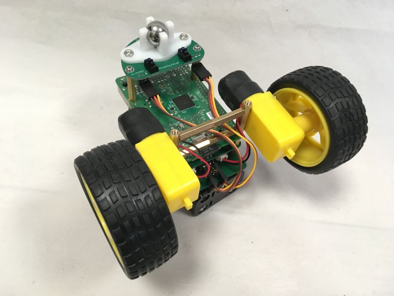

Use the servo leads to connect the line sensors from the caster board to the male header on the PiBug main board. Ensure the correct orientation of the cable: Brown wire should be on the robot’s right side of the castor board (labelled ‘G’) and on the bottom of the header on the PiBug board (labelled Gnd). Use the leftmost and rightmost positions for the cables
Step 9 – Fitting the Optional Ultrasonic Distance Sensor
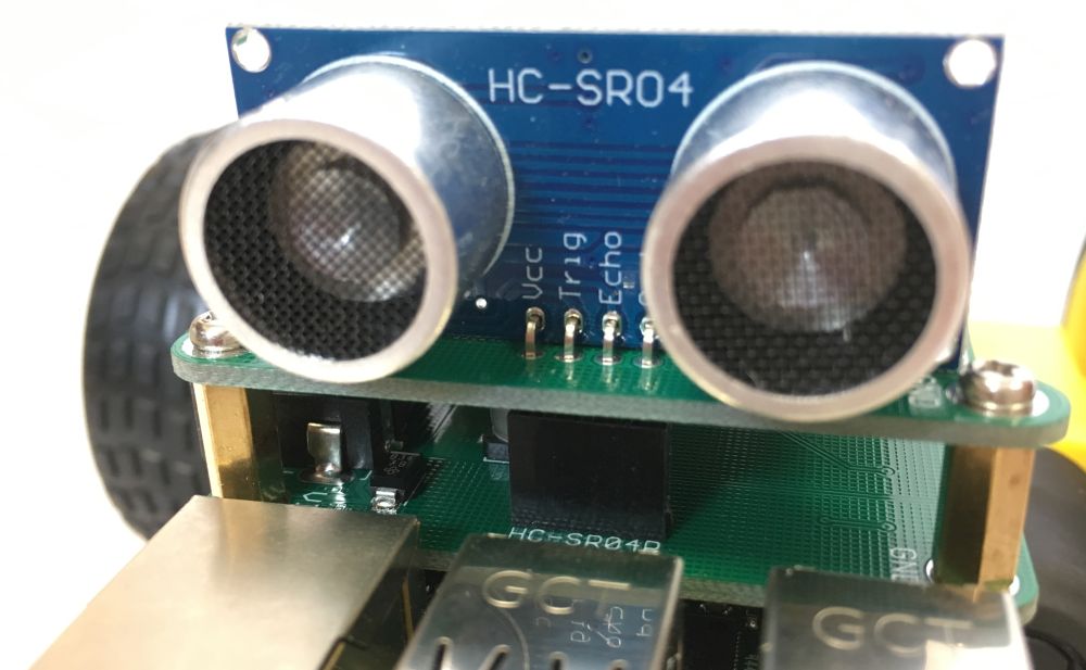
- Use a HC-SR04P which is 3.3V compatible. Do not use the older HC-SR04.
- Remove the black plastic spacer, so that it can push all the way down.
- Plug it through the 4 holes in the battery board and push it all the way down (see photo above)
- The sensor is now connected to pin 20 on the Raspberry Pi
NB. We have also sold the HC-SR04+ for this purpose. it doesn’t need modifying by removing the spacer, but it is a little shorter and may need holding in to keep a good connection.
You have now completed the buggy and all you need to do is code it!
Coding PiBug
Pins used:
Left motor: #19, #26
Right motor: #16, #21
Ultrasonic: #20
Line sensors: #04, #27
Tact switch: #13
There are also 2 spare GVS style connectors which you can use for what you want on #17 and #18
A PiBug library module and example code is available by running the following commands in a terminal window on your Pi
- wget https://4tronix.co.uk/pibug.sh -O pibug.sh
- bash pibug.sh