PiStep2 Dual & Quad Stepper Controller for Raspberry Pi

PiStep2 Stepper Controllers for Raspberry Pi

PiStep2 is the new (May 2016) release of PiStep which has been a standard stepper motor controller for Raspberry Pi for a couple of years. PiStep2 changes the GPIO header to a 40 pin version, compatible with all Raspberry Pis since B+. This includes A+, B+, 2B, 3B and Zero.

In addition, the ULN2803, which is the Darlington driver chip, has been replaced by a surface mount version. This allows us to fit twice as many stepper motor channels on roughly the same area of PCB

To keep the cost similar to the older, 2-channel only PiStep, we offer a Dual version of the new PiStep as well as the quad version.

Purchase PiStep2 Here


Pistep2 Pinout

PiStep2 uses a single GPIO pin for each of the stepper drive outputs. There are 4 drivers per stepper motor, so a total of 16 GPIO pins are used.

  • MOTOR 1:  Physical pins 11, 12, 13, 15  (GPIO 17, 18, 27, 22)
  • MOTOR 2:  Physical pins 16, 18, 22, 7  (GPIO 23, 24, 25, 04)
  • MOTOR 3:  Physical pins 33, 32, 31, 29  (GPIO 13,12,6,5)
  • MOTOR 4:  Physical Pins 38, 37, 36, 35  (GPIO 20,26,16,19)


To drive the stepper motors you must change the pins that are enabled in a specific sequence – using either a 4-step or an 8-step sequence. You can reverse the sequence to make the stepper motors go the opposite way. See Matt from Raspberry Pi Spy’s excellent article here.


PiStep2 Jumper Settings

NB. PiStep2 v2.1 has the jumper settings marked incorrectly; Setting to the left (marked Vcc) is actually Vin, for voltage from 2-pin screw terminal. Setting to the right (marked Vin) is actually for using the 5V

Although you can have all four stepper motors connected to the Pi at the same time, it is unlikely that you can have them all moving simultaneously. This is because the total current required will exceed that available from the Pi. For this reason the Pistep2 (like the older PiStep) provides options to add extra power to the 5V line via the on-board micro-USB connector, or to add a completely separate power supply (up to 9V for standard “5V” stepper motors). The small jumper selects which power supply to use. If the jumper is to the right (nearest the micro-USB connector) then it will use the 5V on the board (which can be supplemented with external 5V into the USB), and if it is to the left then it will use the voltage supplied into the 2-pin screw terminal.


PiStep2 Example Software

There are 2 python examples that we provide. Both of these are based on Matt’s software from the link above.

  • stepper.py simply rotates a single stepper motor at a fixed speed. Edit the code to change to using a different motor
  • stepctrl.py places the main sequencing code into a separate thread and then uses keyboard input to select which motor, if any, is operating.

Placing the sequencing into a separate thread makes it possible for the stepper motor to carry on turning while the main program looks at sensors or user inputs to decide what to do next. I intend to create a simple library that allows the a separate thread to be easily created for each motor, enabling change of speed and direction very simply from the main program – not available yet however.



Ar2Pi2 – Dual Mode Robot – Arduino vs Raspberry Pi

Ar2Pi2 – The Robot That Can be Arduino or Raspberry Pi

(Previously known as BotZero)

Click on any photo to enlarge.

botzero03a

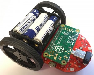
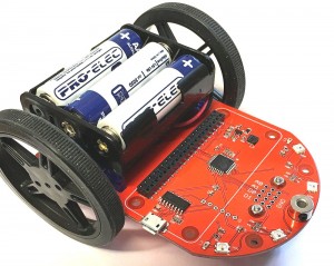
Ar2Pi2 as an Arduino Uno compatible robot


botzero07

Ar2Pi2 as a Raspberry Pi robot


Overview

Ar2Pi2 is a tiny robot that fits well inside the boundaries of an A6 sheet of paper (148 x 105mm). This makes it ideal for Micro Pi Noon and other small robot competitions.

Including the wheels it is 110 x 90mm and is 60mm high

The robot contains an ATMega328 which can be programmed over the USB interface just like an Arduino Uno. The robot is then fully programmable using any of the standard Arduino methods. A simple demo program is BotZMotor.ino

Alternatively, you can program the ATMega328 with the BotZero01.ino code and plug in your Raspberry Pi Zero and use the Pi to control the robot. This is very similar to the way our Picon Zero intelligent robotic controller works (in fact they share a lot of the same code). In this Raspberry Pi mode, there is a full Python library to enable you to control everything on the robot from python running on the Pi

The whole robot is powered by 3 AA cells. There is an onboard “boost” regulator to generate the 5V needed for the Pi.


Features

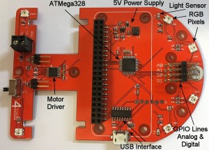
  • Hardware controlled by ATMega328
  • Powered by 3xAA batteries
  • 6 x RGB pixels (mini “neopixels”)
  • 2 x Analog light sensors
  • 2 x Analog line following sensors
  • 2 x DC motors fitted in servo cases
  • Large 60mm diameter wheels
  • Front smooth running caster
  • USB interface to the ATMega328
  • 4 x general purpose I/O lines with GVS (Ground, Volts, Signal) 3-pin connections. These can be Digital or Analog etc (just like Picon Zero)
  • On/Off switch
  • Special fitting for Micro Pi Noon balloon holder and popper (If this is fitted, the 4 I/O lines GVS pins cannot be used)
  • Designed for Raspberry Pi Zero, but other Raspberry Pis could be fitted by using a suitable extension header


Pictorial Overview

botzero05a


Assembling the Kit

Step 1 – Attach the Bottom plate and mounting pillars

step01a

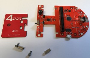
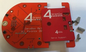
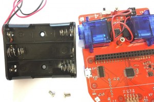
Check you have the bottom mounting plate, 2 pan-head screws and 2 10mm pillars

step01b

Orient the bottom plate so the holes clear the soldered components as shown

step01c

Push the screws through the bottom plate and the main board, then screw into the 10mm pillars

step01d


Step 2 – Attach the Motors

step02a

All you need is the motors. Ensure the wires exit from the back of the motors and the red wires are both on the inside as shown

step02b

Carefully twist the wires so they fit between the motors, ensuring they don’t go over the motors


Step 3 – Fit the Battery Holder

step03a

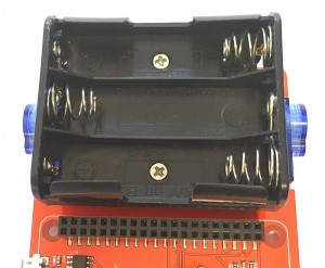
You’ll need the battery holder and 2 countersink head screws

step03b

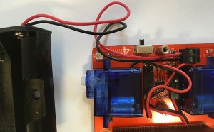
First connect the battery holder to the screw terminals. Red towards the rear, marked Vin

step03c

Twist the wires in between the 2 motors – again being careful that the wires do not get trapped between the motors and the battery holder. Warning: this is tricky! You can leave the wires out which is much easier, but it doesn’t look as tidy, so it is worth persevering.


Step 4 – Fit the Front Caster

step04a

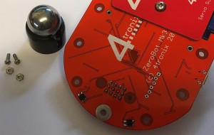
Use the short 6mm screws (in the separate bag of screws and pillars) and note that the spacers provided with the caster are not required

step04b

With the ball out of the holder, push the screws through the black holder and through the PCB

step04c

Screw the nuts on tight

step04d

Finally, push the steel ball into the holder. It should snap tightly in and move very smoothly


Step 5 – Attach the Wheels

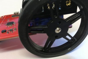
step05a

First stretch the tyres over the plastic wheels. Then push the wheels onto the shafts of the motors

step05b

Use the screws provided to tightly fix the wheels


Your Ar2Pi2 is ready to rock and roll!

Add batteries and switch it on to demo the LEDs and the motor operations. Next step, write some programs…


Download the python library and examples from here