Picocon – The “No Frills” Motor Controller
Purchase Here
Scroll down for the assembly information for v1 of Picocon (Yellow PCB)
Assembling your PicoCon
1. Check You Have Everything
- PCB (Red)
- 3 x Screw Terminal Blocks
- Dual H-Bridge Chip
- 100nF capacitor
- Diode
- 6-pin female header
- 10-pin female header
- 26-pin female (GPIO) header
2. Start with the Diode
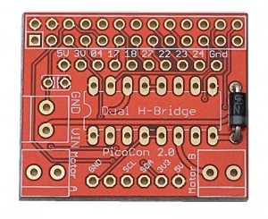
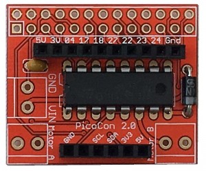
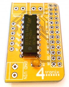
Ensure that the white line on the diode is facing the bottom as shown in the photo above. Solder it carefully then snip the leads off underneath
3. Add the Capacitor
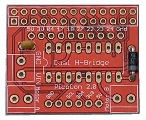
This can be placed either way round. Mount it close to the PCB as shown
4. Add the H-Bridge Chip
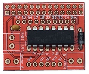
This must be placed the correct way round or it will be damaged. Check the orientation twice before soldering!
The writing ion the chip should be correct way up when viewed as in the photo above. The little ‘U-shaped’ notch should be on the left
Click on the image above to enlarge it to see the orientation more clearly
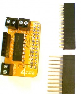
5. Add the 2 Female Headers
It is a good idea to add these both at once as the board will rest on them on your desk fairly firmly.
Solder just one pin on each initially. Then pick up and for each header, melt the solder again while holding the header and move it until it is straight and level.
Then solder the remaining pins. It is difficult to straighten them up after more than one or two pins have been soldered, so do it at the beginning.
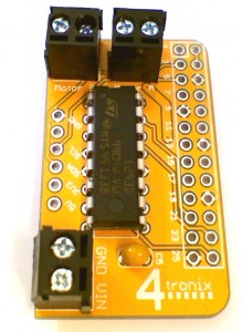
6. Add the 2-pin Screw Terminals
As with the female headers, add them all together so the board rests on them when soldering the first pin of each
Straighten them out before soldering the second pin, in the same way you did for the female headers
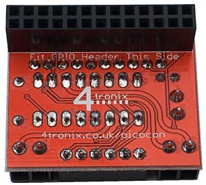
7. Finally add the GPIO Header
Make sure you add it on the bottom of the board!
Again, just solder one pin at each end then adjust until it is straight. Then solder the remaining pins
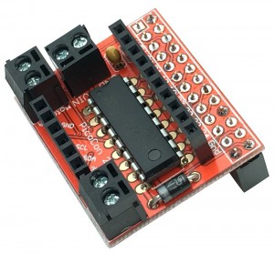
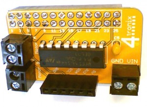
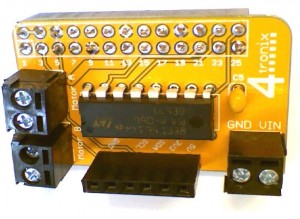
Your board should now look like this
Software for your PicoCon
1. Basic python software
- Each motor is directly controlled by two pins, each of which drives one side of the motor
- To make the motor go forwards, you make one pin high and the other pin low
- To make it reverse, you make the first pin low and the second pin high
- For the robot to go forwards both motors should be set to forwards
- Similarly to go backwards, both motors should be set to reverse
- If you set the left motor to forwards and the right motor to backwards, the robot will spin right
- The (physical) pins for the left motor are 19 and 21
- The (physical) pins for the right motor are 24 and 26
- So to make the left motor go forwards, set pin19 high and pin21 low. You can do this in python with:
GPIO.output(19, 1) # pin 19 is left motor A
GPIO.output(21, 1) # pin 21 is left motor B
This is covered in a complete python program picoTest01.py covered below.
2. Using the supplied python library
- You need to import the library at the start of your python program
import picocon - Then you can use the pre-defined functions for moving the motors:
- init(). Initialises GPIO pins, switches motors off, etc
- cleanup(). Sets all motors off and sets GPIO to standard values
- stop(): Stops both motors
- forward(speed): Sets both motors to move forward at speed. 0 <= speed <= 100
- reverse(speed): Sets both motors to reverse at speed. 0 <= speed <= 100
- spinLeft(speed): Sets motors to turn opposite directions at speed. 0 <= speed <= 100
- spinRight(speed): Sets motors to turn opposite directions at speed. 0 <= speed <= 100
- turnForward(leftSpeed, rightSpeed): Moves forwards in an arc by setting different speeds. 0 <= leftSpeed,rightSpeed <= 100
- turnReverse(leftSpeed, rightSpeed): Moves backwards in an arc by setting different speeds. 0 <= leftSpeed,rightSpeed <= 100
- To use these functions, you need to preface them with the name of module, picocon.
- You need to call the function init() at the start of your program to setup all the input and output pins
picocon.init() - You must call the cleanup() function at the end to put all the input and output pins back to where they were
picocon.cleanup() - In between you can do whatever you want, so to make the robot go forwards at a medium speed:
picocon.forward(50) - to spin left at a fast speed
picocon.spinLeft(100)
Downloading the Software Library and Examples
- Make sure the Pi is connected to the internet
- From a terminal window on your Pi type the following lines exactly:
wget http://4tronix.co.uk/picocon.sh -O picocon.sh
bash picocon.sh - This will create a new folder on your Pi called picocon
- Go into this folder and then you can run the examples like this:
sudo python picoTest01.py - picotest01.py simply goes forwards, backwards, spins right and left in a loop. Press Ctrl-C to exit
- picotest02.py does the same thing but using the library (see how much simpler the code is)
- picotest03.py uses the arrow keys on your keyboard to move the robot. You can also use . or , to speed up and slow down the robot. Also use space to stop
—————————————————————–
Following information for Picocon v1 (Yellow)
The PicoCon is a very basic “No Frills” motor controller that lets you get going with robots very quickly and simply.
Assembling your PicoCon
1. Check You Have Everything
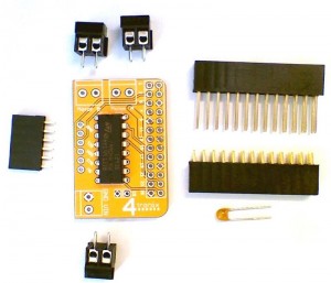
The are only 7 components to solder to the PCB:
- L293D Dual H-Bridge chip
- 3 x Screw Termianls 2-pin
- Capacitor 100nF
- 6-way Female Header
- GPIO Header (short and long pin are provided – select which one to use)
2. Solder in the L293D
Solder the main IC – make sure pin one is in the correct place and do NOT spend too long with the soldering iron held against a pin as it may damage the chip. 2 to 3 seconds at most
3. Add the 100nF Capacitor
Add the small capacitor. It doesn’t matter which way around this goes
4. Fit the Screw Terminals
Then add the 3 screw-terminal blocks for the 2 motors and the motor power
5. Fit the 6-Pin Female Header
Connect the 6-pin I2C breakout connector (Very useful if you want to plug in the IP Display so you know the IP address of your robot)
6. Select the GPIO Header to use
If you use the extended header, then it allows you to easily access the GPIO pins not used by the Picocon itself. However, it then makes the Picocon very easy to short out and much more delicate. Choose wisely!
7. Attach the GPIO Header to the UNDERSIDE of the PCB
Finally solder the GPIO head to the REVERSE SIDE of the board. Once on, it is very difficult to remove. So make sure you get it right

