Pi2Go Mk2 Programming

Programming the Pi2Go Mk 2

Preparing your Raspberry Pi

Before you can install the Pi2Go Mk 2 software, you will need to ensure that your Raspberry Pi is up and running and connected to the internet. You will need to be able to see the desktop or console (either using direct connections, or SSH or VNS over the network).

Setting up a Raspberry Pi is not covered here. It is best to get the information from the source at Raspberry Pi

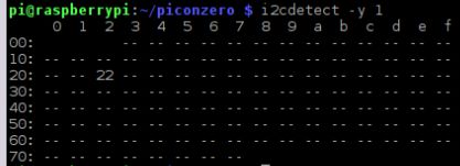
You will also need to enable SPI and I2C. Do this from raspi-config

sudo raspi-config

Select interfaces and enable both SPI and I2C. Then reboot.

Using with ScratchGPIO

Simplesi (Simon Walters) has generously included Pi2Go Mk2 in the list of directly supported devices in ScratchGPIO.

Visit this blog post for installation and coding tips

Installing the Pi2Go Mk2 Python Software

NB. Note that this software is still in Python 2. Python 3 will not work due to Print statements. Hopefully this will be resolved shortly

First you will need to prepare your Pi for the Smart RGB LEDs (fully compatible with neopixels). The best way we’ve found to do this is run Pimoroni’s curl script.
With your Pi connected to the internet, run (you don’t need to install the resources and examples):

curl -sS https://get.pimoroni.com/unicornhat | bash

Download the Python library module and example software for Pi2Go Mk2 with

wget https://4tronix.co.uk/pi2go2.sh -O pi2go2.sh

bash pi2go2.sh

This installs the following, which should be run in Python 2 for now (unless otherwise stated)

  • ipd.desktop in home/pi/.config/autostart which will start the IP Display on boot. This will silently fail if the optional IP Display is not plugged into either port.
  • Creates a folder home/pi/pi2go2 for all the example files and library module pi2go2.py (the main library module)
  • motorTest.py to demonstrate driving the motors. Must be run in a terminal, not from an IDE like Idle or Thonny. Use LXTerminal for this
  • stepTest.py to demonstrate running motors controlled by the wheel sensors. Must be run in a terminal, not from an IDE like Idle or Thonny. Use LXTerminal for this
  • adc.py shows the light sensor values and raw battery voltage
  • ledTest.py flashes all LEDs through Red, Green, Blue and White. This must be run using sudo. ie: sudo python3 ledTest.py
  • rainbow.py sets the LEDs to rainbow colours (static, but flashes every 10 seconds). This must be run using sudo in Python 3. ie: sudo python3 rainbow.py
  • lineTest.py shows the value of the line sensors
  • lineFollower.py is very basic line follower program
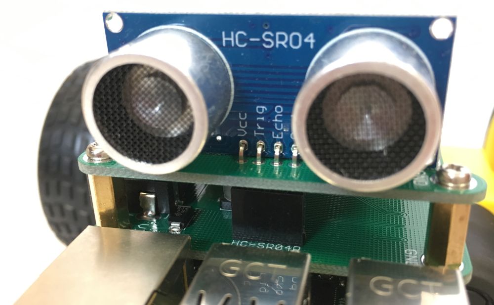
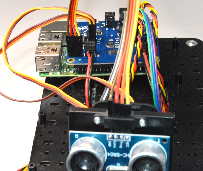
  • sonarTest.py shows the distance in cm for an obstacle using the optional ultrasonic breakout in either or both expansion slots
  • ipd03.py this is the program run on boot up to display the IP address of the Pi to make it easy to connect to using VNC or SSH

Using the Pi2go2.py Library Module

To use this module, you must first import it into your program using

import pi2go2

Then, before using any other functions you should call the init ( ) function to initialise all the variables used by the library. The init ( ) function has an optional parameter which is the default brightness of the LEDs. If omitted, this defaults to 40. So the following call will initialise the library and set the default brightness to 100:

pi2go2.init (100)

Hot Tip:
As a special case, if you set the brightness to zero, then the LEDs are not initialised. As this would require use of the sudo command, it can be beneficial to call init (0) so that your program can be run without using sudo.

When your program has finished, it is good practice to close down everything tidily by calling:

pi2go2.cleanup ( )

Motor Functions

  • stop ( ): Stops both motors – coast slowly to a halt
  • brake ( ): Stops both motors – brakes quickly
  • forward (speed): Sets both motors to move forward at speed. 0 <= speed <= 100
  • reverse (speed): Sets both motors to reverse at speed. 0 <= speed <= 100
  • spinLeft (speed): Sets motors to turn opposite directions at speed. 0 <= speed <= 100
  • spinRight (speed): Sets motors to turn opposite directions at speed. 0 <= speed <= 100
  • turnForward (leftSpeed, rightSpeed): Moves forwards in an arc by setting different speeds. 0 <= leftSpeed,rightSpeed <= 100
  • turnreverse (leftSpeed, rightSpeed): Moves backwards in an arc by setting different speeds. 0 <= leftSpeed,rightSpeed <= 100


Wheel Sensor Functions

  • stepForward (speed, steps): Moves forwards specified number of steps, then stops
  • stepReverse (speed, steps): Reverses specified number of steps, then stops
  • stepSpinL (speed, steps): Spins left specified number of steps, then stops
  • stepSpinR (speed, steps): Spins right specified number of steps, then stops


RGB LED Functions

  • setColor (color): Sets all LEDs to color – requires show()
  • setPixel (ID, color): Sets pixel ID to color – requires show()
  • show ( ): Updates the LEDs with state of LED array
  • clear ( ): Clears all LEDs to off – requires show()
  • rainbow ( ): Sets the LEDs to rainbow colors – requires show()
  • fromRGB (red, green, blue): Creates a color value from R, G and B values
  • toRGB (color): Converts a color value to separate R, G and B
  • wheel (pos): Generates rainbow colors across 0-255 positions

IR Sensor Functions

  • irLeft ( ): Returns state of Left IR Obstacle sensor
  • irRight ( ): Returns state of Right IR Obstacle sensor
  • irAll ( ): Returns true if either of the Obstacle sensors are triggered
  • irLeftLine ( ): Returns state of Left IR Line sensor
  • irRightLine ( ): Returns state of Right IR Line sensor

UltraSonic Function

  • getDistance (sonar = 0). Returns the distance in cm to the nearest reflecting object. 0 == no object. Sonar 0 is the front connector, Sonar=1 is the side connector. If you don’t include the parameter it defaults to 0 (front)

    Analog and Light Sensor Functions

  • getLight (Sensor). Returns the value 0..1023 for the selected sensor, 0 <= Sensor <= 3
  • getLightFL ( ). Returns the value 0..1023 for Front-Left light sensor
  • getLightFR ( ). Returns the value 0..1023 for Front-Right light sensor
  • getLightBL ( ). Returns the value 0..1023 for Back-Left light sensor
  • getLightBR ( ). Returns the value 0..1023 for Back-Right light sensor
  • getBattery ( ). Returns the voltage of the battery pack (>7.2V is good, less is bad)

    Switch Function

  • getSwitch ( ). Returns the value of the tact switch: True == pressed

Pi2Go Mk 2 Home Page

Links

Overview

The Pi2Go Mk2 is the evolution of the very popular original Pi2Go, first shipped in April 2015. The major changes are:

  • Improved assembly method, particularly the motor mounts
  • No wires for attaching the battery packs
  • Better quality wheels with high grip tyres
  • Wheel sensors built into both wheels
  • Programmatic access to the raw battery voltage
  • Improved analog light sensors – one in each corner
  • 10 individually addressable Smart RGB LEDs
  • 2 edge connectors compatible with Pimoroni’s Breakout Garden with full access to I2C signals and individual GPIO signals
  • Improved motor controller allowing higher speeds and optional braking on stop
  • Now with 4WD option


Specification

  • Requires 6 x AA rechargeable battery cells (not included)
  • Supports all versions of 40-pin Raspberry Pi
    (NB. the Raspberry Pi 4 consumes a lot of power and it is recommended to use one of the optional 7 x AA, or 2 x 18650 battery boards)
  • Motor controller: DRV8833
  • Analog input (light sensors and battery) MCP3008
  • Switching 5V power supply using TPS5430
  • 10 x SK6812-3535 Smart RGB LEDs (compatible with neopixels) – on battery board
  • On/Off switch with Blue indicator LED – on battery board
  • 2 x TCRT5000 infra-red obstacle sensors (front corners)
  • 4 x SFH3710 light sensors (all 4 corners)
  • 2 x TCRT5000 infra-red line follower sensors
  • 6mm tact switch for programmatic use
  • 4 x servo connections – direct from GPIO pins, with 5V and Gnd signals
  • 2 x optical wheel sensors with 20 slot encoder wheels (ie. 20 pulses per revolution)
  • 2 slots for breakout boards, including ultrasonic distance sensor and IP Display. These slots are compatible with Pimoroni’s Breakout Garden range.
  • Overall size with wheels attached: 148 x 118 x 98mm (length x width x height)
  • Weight (excluding Raspberry Pi & batteries): 282g


GPIO Connections

(Broadcom numbering)

  • Left Motor: 26, 19
  • Right Motor: 21, 16
  • Smart RGB LEDs: 18
  • Left Obstacle Sensor: 22
  • Right Obstacle Sensor: 17
  • Left Line Sensor: 23
  • Right Line Sensor: 27
  • Front ultrasonic (or general I/O): 20
  • Side ultrasonic (or general I/O): 4
  • Tact switch: 15
  • Left wheel sensor: 5
  • Right wheel sensor: 6
  • Servos: 12, 13, 24, 25


Scooter for Raspberry Pi Zero

Scooter Robot for Raspberry Pi Zero

Purchase Scooter

Assembly

Step 1 – Check you have all the parts

  • Main board with attached battery holder
  • 2 x wheels
  • 2 x 16mm pillars
  • 4 x screws
  • Female header

Step 2 – Remove the Battery Holder

Unscrew the battery holder, taking careful note of which way it is fitted


Step 3 – Fit the Raspberry Pi Zero

NB. You need to have a Pi Zero with the headers fitted. Model Zero WH is recommended

Screw the 16mm pillars onto the main board

Push the included female header into the low-profile header on the main board

Fit the Pi Zero to the header, with the Pi Zero sitting over the motors as shown below

Screw the Pi Zero onto the headers so it doesn’t fall off in use


Step 4 – Complete the Assembly

Refit the battery holder

Push on the wheels

Add batteries

Start coding…

Coding for the Scooter

Install the software

First you will need to prepare your Pi for the Smart RGB LEDs (fully compatible with neopixels). The best way we’ve found to do this is run Pimoroni’s curl script.
With your Pi connected to the internet, run (you don’t need to install the resources and examples):

curl -sS https://get.pimoroni.com/unicornhat | bash

Then install the Scooter software:

wget https://4tronix.co.uk/scooter.sh -O scooter.sh

bash scooter.sh

This installs the following files:

  • scooter.py the main library module
  • motorTest.py Use the arrow keys to control the motors. Use . and , to speed up and slow down after next arrow press. Press space bar to stop slowly and ‘b’ to brake quickly
  • ledTest.py Sets the Smart RGB LEDs to Red, Green, Blue, White in turn. Run with sudo python ledTest.py
  • lineTest.py shows the states of the line follower sensors
  • sonarTest.py gives the distance in cm to an obstacle using the optional HC-SR04P
  • avoider.py is a simple obstacle avoider. Run with sudo python avoider.py
  • lineFollower.py is a simple line follower. This runs the Scooter backwards and is best with lines printed from RobotSquare.


Pi2Go Mk2 Assembly

Assembly Instructions for Pi2Go Mk2

Click any image to enlarge

Step 1 – Check the Contents

Check you have:

  • Main Board
  • Battery Board
  • Caster Board
  • 2 Wheels
  • 2 Motors
  • 2 Motor Fixings Bags
  • Bag with mechanical parts (caster, encoder disks, headers)
  • Fixings Bag with screws and spacers

Fixings bag contains:

  • 4 x 5mm, M3, Male-Female pillars
  • 4 x 11mm, M2.5 Male-Female pillars
  • 4 x 19mm, M2.5 Female-Female pillars
  • 2 x 24mm, M3, Female-Female pillars
  • 4 x 4mm, M3 screws
  • 4 x 8mm, M3 screws
  • 8 x 6mm, M2.5 screws


Step 2 – Fit the Raspberry Pi Mountings

You will need 4 x 19mm, M2.5 pillars and 4 x 6mm, M2.5 screws.

Fit the 4 pillars to the main board as shown below


Step 3 – Prepare the Motor Mounts

Screw 2 of the 5mm, M3 pillars into the top of each motor mount. Ensure they are fitted tightly


Step 4 – Fit the Motor Mounts to the Motors

Pass one of the long screws from the outside of the motor (the side without the wires), through the motor and through the motor mount. Then loosely fit one of the nuts. It will sit at a strange angle as shown below

Then pivot the mount on the long nut, so that it pushes the wires out of the way and allows you to put the second long screw in. Then tighten up both nuts.

Repeat for the second motor, but fit the mount the other way up.

You should now have a left-hand and a right-hand motor assembly as shown above

Step 5 – Fit the Motor Assemblies to the Main Board

First, attach an encoder wheel to the inside shaft of each motor. Just push it on so that it is flush with the end of the shaft. It may take some pushing to get it on, and when it is on it will be a bit floppy. This is normal

Now use the 4mm, M3 screws, 2 for each motor, to screw through the main board into the pillars that you fitted into each motor mount in step 3


Step 6 – Assemble the Front Caster board

Use 2 of the 8mm, M3 screws to screw through the caster, through the caster PCB and into the 24mm, M3 pillars. Ensure the header pins are on the opposite side to the caster, and the same side as the pillars.


Step 7 – Fit the Caster Board to the Main Board

First push the extended 6-pin header into the header on the bottom of the main board, then plug the assembled caster board into the 6-pin header as shown below

Finally screw the 2 remaining 8mm, M3 screws through the main board and into the top of the pillars from the caster board. Tighten up well.


Step 8 – Fit the Raspberry Pi

You can use a Model A, A+, B or B+.

NB: To use a Raspberry Pi Zero, use the “Zero Spacer” PCB that is included with Pi2Go Mk2 since 1st September 2019. Kits shipped prior to that date do not include that spacer so you would have to use washers or similar to make up the extra 1.6mm height.

Push the 40-pin header onto the header on the main board

Then push the Raspberry Pi, upside down, into the 40-pin header, ensuring that all the pins line up and the mounting holes on the Raspberry Pi match the pillars

Screw the 11mm, M2.5 Male-Female pillars in well to hold the Pi firmly


Step 9 – Fit the Battery Board

Standard 6 x AA battery board shown. Fitting the other types is the same

Making sure that the LEDs marked 0 through 7 are at the front, use the 6mm, M2.5 screws to fix the battery board tightly to the 4 pillars.
Note that these pillars all carry power and/or signals, so it is important that they are all screwed in well. Failure to attach screws or pillars properly will result in failure of the Pi2Go.


Step 10 – Add the Wheels

Push on the wheels

And the build is complete!

Now go to the Programming Pi2Go Mk2 article to get it going


PiBug Assembly and Coding

PiBug

Click on any image to enlarge

A barebones, but sturdy, 2WD buggy for the Raspberry Pi, that uses the Pi itself as the chassis for the robot.

Purchase PiBug Here

Assembling the PiBug

Step 0 – Check you have all the parts

  1. Main board
  2. Caster board
  3. Battery board
  4. Battery holder
  5. Castor Pack containing:
    1. Castor ball and housing
    2. Screws: M3, 6mm X 2
    3. Nuts: M3 X 2
  6. Fixings Pack containing:
    1. 22mm F-F pillars X 2
    2. 22mm M-F pillars X 2
    3. 30mm Pillars with holes X 2
    4. 25mm F-F pillars X 2
    5. 9mm M-F pillars X 8
    6. 6mm M2.5 screws X 6 (2 for the caster board)
    7. 30mm M2.5 screws X 4
  7. Motors X 2
  8. Wheels X 2

Step 1 – Attach the Castor to the Castor board

Put the M3 nuts in the holes in the castor housing, then use the 6mm M3 screws to fit the housing tightly to the castor board as shown, with the castor on the bottom and the large 4tronix logo on the top.

Step 2 – Assemble the Motor Mounts

  1. Screw a 22mm Male-Female pillar into a 22mm Female-Female pillar tightly, making a 44mm female-female spacer (remember: 22mm is not the same as 25mm)
  2. Repeat to create a second 44mm spacer
  3. Thread the 30mm screws through the holes in the motor and through the holes in the side of the 30mm pillars, then screw into the 44mm spacers
  4. Important: The 30mm pillars with holes have one end rounded for about 1mm. This is the bottom, the other end is the top that fits to the Raspberry Pi. The rounded end is tapped for M3, and the hex end is tapped for M2.5. Ensure you have these the correct way up
  5. Ensure that the motors shafts are facing outwards as shown in the photo

Step 3 – Fit Motor mounts to Raspberry Pi

You can use either Model A or Model B varieties of Pi. You can’t use a Zero (at least not without some ingenuity…)

  1. In this step we will use 4 of the 9mm pillars
  2. Screw the threaded end of the 9mm pillars through the 2 holes in the SD card end of the Raspberry Pi and into the top of the 30mm pillars of the motor mount assembly
  3. Ensure all screws are tightly fastened

Step 4 – Fit the Castor assembly to Raspberry Pi

  1. Use 2 of the 6mm M2.5 screws to attach the 25mm pillars to the top of the castor board
  2. Use the 2 more of the 9mm pillars and screw through the holes in the Pi into the top of the 25mm pillars as shown

Step 5 – Fit the PiBug Main Board

  1. Push the PiBug main board onto the GPIO connector of the Pi. Ensure all the pins are lined up properly and that the holes on the PiBug board line up with the 9mm pillars
  2. Use the threaded ends of the 4 remaining 9mm male-female pillars to fit the PiBug main board into position.

Step 6 – Fit the Battery Holder Board

Use the 4 remaining 6mm, M2.5 screws to fit the battery holder PCB as shown, with the snap connectors at the USB/ethernet end of the Raspberry Pi

Step 7 – Connecting it up

  1. Connect the JST leads from the motors into the appropriate motor connector on the PiBug board
  2. Fit 6 AA rechargeable batteries into the battery holder and then plug it into the connectors on the battery board.
  3. Note that it will work with alkaline batteries, but when the batteries get low it may suddenly reset the Pi when changing motor direction. This behaviour is better with rechargeable batteries.
  4. We recommend that you use a velcro strap or similar to hold the battery pack in place in case of accidents

Step 8 – Fitting the Optional Line Sensor Board

Use the servo leads to connect the line sensors from the caster board to the male header on the PiBug main board. Ensure the correct orientation of the cable: Brown wire should be on the robot’s right side of the castor board (labelled ‘G’) and on the bottom of the header on the PiBug board (labelled Gnd). Use the leftmost and rightmost positions for the cables

Step 9 – Fitting the Optional Ultrasonic Distance Sensor

  1. Use a HC-SR04P which is 3.3V compatible. Do not use the older HC-SR04.
  2. Remove the black plastic spacer, so that it can push all the way down.
  3. Plug it through the 4 holes in the battery board and push it all the way down (see photo above)
  4. The sensor is now connected to pin 20 on the Raspberry Pi

NB. We have also sold the HC-SR04+ for this purpose. it doesn’t need modifying by removing the spacer, but it is a little shorter and may need holding in to keep a good connection.

You have now completed the buggy and all you need to do is code it!

Coding PiBug

Pins used:

Left motor: #19, #26

Right motor: #16, #21

Ultrasonic: #20

Line sensors: #04, #27

Tact switch: #13

There are also 2 spare GVS style connectors which you can use for what you want on #17 and #18

A PiBug library module and example code is available by running the following commands in a terminal window on your Pi

  • wget https://4tronix.co.uk/pibug.sh -O pibug.sh
  • bash pibug.sh


Ar2Pi2 – Dual Mode Robot – Arduino vs Raspberry Pi

Ar2Pi2 – The Robot That Can be Arduino or Raspberry Pi

(Previously known as BotZero)

Click on any photo to enlarge.

botzero03a

Ar2Pi2 as an Arduino Uno compatible robot


botzero07

Ar2Pi2 as a Raspberry Pi robot


Overview

Ar2Pi2 is a tiny robot that fits well inside the boundaries of an A6 sheet of paper (148 x 105mm). This makes it ideal for Micro Pi Noon and other small robot competitions.

Including the wheels it is 110 x 90mm and is 60mm high

The robot contains an ATMega328 which can be programmed over the USB interface just like an Arduino Uno. The robot is then fully programmable using any of the standard Arduino methods. A simple demo program is BotZMotor.ino

Alternatively, you can program the ATMega328 with the BotZero01.ino code and plug in your Raspberry Pi Zero and use the Pi to control the robot. This is very similar to the way our Picon Zero intelligent robotic controller works (in fact they share a lot of the same code). In this Raspberry Pi mode, there is a full Python library to enable you to control everything on the robot from python running on the Pi

The whole robot is powered by 3 AA cells. There is an onboard “boost” regulator to generate the 5V needed for the Pi.


Features

  • Hardware controlled by ATMega328
  • Powered by 3xAA batteries
  • 6 x RGB pixels (mini “neopixels”)
  • 2 x Analog light sensors
  • 2 x Analog line following sensors
  • 2 x DC motors fitted in servo cases
  • Large 60mm diameter wheels
  • Front smooth running caster
  • USB interface to the ATMega328
  • 4 x general purpose I/O lines with GVS (Ground, Volts, Signal) 3-pin connections. These can be Digital or Analog etc (just like Picon Zero)
  • On/Off switch
  • Special fitting for Micro Pi Noon balloon holder and popper (If this is fitted, the 4 I/O lines GVS pins cannot be used)
  • Designed for Raspberry Pi Zero, but other Raspberry Pis could be fitted by using a suitable extension header


Pictorial Overview

botzero05a


Assembling the Kit

Step 1 – Attach the Bottom plate and mounting pillars

step01a

Check you have the bottom mounting plate, 2 pan-head screws and 2 10mm pillars

step01b

Orient the bottom plate so the holes clear the soldered components as shown

step01c

Push the screws through the bottom plate and the main board, then screw into the 10mm pillars

step01d


Step 2 – Attach the Motors

step02a

All you need is the motors. Ensure the wires exit from the back of the motors and the red wires are both on the inside as shown

step02b

Carefully twist the wires so they fit between the motors, ensuring they don’t go over the motors


Step 3 – Fit the Battery Holder

step03a

You’ll need the battery holder and 2 countersink head screws

step03b

First connect the battery holder to the screw terminals. Red towards the rear, marked Vin

step03c

Twist the wires in between the 2 motors – again being careful that the wires do not get trapped between the motors and the battery holder. Warning: this is tricky! You can leave the wires out which is much easier, but it doesn’t look as tidy, so it is worth persevering.


Step 4 – Fit the Front Caster

step04a

Use the short 6mm screws (in the separate bag of screws and pillars) and note that the spacers provided with the caster are not required

step04b

With the ball out of the holder, push the screws through the black holder and through the PCB

step04c

Screw the nuts on tight

step04d

Finally, push the steel ball into the holder. It should snap tightly in and move very smoothly


Step 5 – Attach the Wheels

step05a

First stretch the tyres over the plastic wheels. Then push the wheels onto the shafts of the motors

step05b

Use the screws provided to tightly fix the wheels


Your Ar2Pi2 is ready to rock and roll!

Add batteries and switch it on to demo the LEDs and the motor operations. Next step, write some programs…


Download the python library and examples from here


Win a Picon Zero and Raspberry Pi Zero!

Win a Picon Zero and Raspberry Pi Zero!

Competition Now Closed

  • You wanted analog inputs for your Raspberry Pi? – You got it!
  • You wanted to drive servos with no difficult software? – You got it!
  • What about driving WS2812 “neopixels” without kernel software that breaks every other release? – You got it!
  • Or maybe you want to get temperature from DS18B20-based sensors without lockouts and waits? – You got it!
  • Oh, and you want to drive a pair of 1.5A per channel DC motors using simple PWM settings? – You got it!
  • And of course, you want it for free? – You (maybe) got it!
  • Hang on, you want a Raspberry Pi Zero for free as well?? – You (maybe) got it!

We’re running a competition: simply retweet the competition tweet to be entered into the draw. On Sunday 3rd April, we will draw the winners:

  • 1st randomly selected, will receive a Picon Zero
  • 2nd randomly selected, will receive a Picon Zero and a Raspberry Pi Zero
  • 3rd randomly selected, will receive a Picon Zero and a Raspberry Pi Zero and a mini robot kit

Postage is FREE anywhere in the world

Competition closes 8pm BST on Sunday 3rd April. Winners will be announced shortly after.

Find out more about the Picon Zero here

Purchase Picon Zero here


 3rd Prize

prize01


2nd Prize

prize01    plus   prize02


1st Prize

prize01  plus  prize02  plus  prize03

Picon Zero – Intelligent Robotics for Raspberry Pi

Picon Zero – Intelligent Robotic Controller for Raspberry Pi

Purchase Picon Zero here

Worksheets now available – see the bottom of this page


Description

The Picon Zero is an add-on PCB for the Raspberry Pi. It is physically the same size as a Raspberry Pi Zero and so is ideal as a pseudo-Hat (pHat) for the Pi Zero. However, it can of course be used on any Raspberry Pi with a 40-pin GPIO connector. Currently that includes the A+, B+, 2B and 3B.

As well as 2 full H-Bridge motor drivers, the Picon Zero has a number of Input and Output pins that can be configured in a variety of ways, allowing you to easily add analog inputs or neopixel outputs to your Raspberry Pi without any complicated software and kernel specific drivers. It also provides an interface for an HC-SR04 ultrasonic distance sensor and opens up 5 GPIO pins from the Raspberry Pi for you to use as you see fit.

The Picon Zero is shipped with all components, including the headers and screw terminals, fully soldered. This saves you doing any soldering and allows you to use it directly from the box


Specification

  • Pseudo-Hat format PCB, 65 x 30 mm with gold plated pads and a ready-fitted 40-pin female header (if using a Pi-Zero, ensure you have soldered a male header in place)
  • 2 full H-Bridge motor drivers. Can drive up to 1.5A continuously (2A peak) per channel, at from 3 – 11V
  • Each motor output has both a 2-pin screw terminal and a 2-pin male header. You choose which to use, depending what connectors you have on the motors
  • The power for the motors can be taken from an external power source (3V to 11V) or from the Picon Zero’s own 5V
  • The Picon Zero’s 5V can be selected to be from the Raspberry Pi’s 5V line, or from a USB connector on the Picon Zero. This allows you to use 2 USB battery banks: one to power the Pi and the other to power the servos and motors on the Picon Zero
  • 4 Inputs that can accept up to 5V. These inputs can be configured as:
    • Digital inputs
    • Analog inputs (10 bits, 0..1023)
    • DS18B20
    • DHT11 (TBD)
  • 6 Outputs that can drive 5V and be configured as:
    • Digital Output (High or Low)
    • PWM Output (Pulse Width Modulation from 0% to 100%)
    • Servo (drives a standard servo through 180 degrees)
    • Neopixel WS2812 (Can drive up to 64 neopixels in a chain. Only available on output 5)
  • All Inputs and Outputs use GVS (Ground, Volts, Signal) 3-pin male headers. This is a common standard for 3-pin sensors and servos and allows direct connection without additional wires
  • 4-pin female header that can connect directly to an HC-SR04 ultrasonic distance sensor. You can plug the sensor directly into this header for an ultra-compact, object avoiding robot
  • 8-pin female header for Ground, 3.3V, 5V and 5 GPIO signals allowing users to add their own additional features


Hardware Configuration

Picon Zero has 2 jumpers for setting the hardware configuration. Make sure you have them set in the correct positions for your requirements

  1. JP1 – Board 5V Selector. This jumper selects where to get the 5V power from for the Picon Zero Outputs. The options are:
    1. Jumper at the top between RPI and 5V. The 5V power for the board is taken from the Raspberry Pi 5V pins on the GPIO connector. With low power output devices and low power 5V motors, this allows you to power all devices with a single 5V power input to the Raspberry Pi
    2. Jumper at the bottom between USB and 5V. The 5V power is taken from the micro-USB connector on the Picon Zero. For higher power out devices, you can provide extra power through the micro-USB connector on the board
  2. JP2 – Motor Power Selector. This jumper selects where to get the power for the motors from. The two options are:
    1. Jumper at the top between Vin and MotorPower. The motors are driven from the 2-pin screw terminal. This voltage can be anything from 3V to 11V. Useful for motors that require a voltage different from 5V, or that require more current than is available on either of the USB input connectors
    2. Jumper at the bottom between 5V and MotorPower. The motors are driven from the board’s 5V power signal. Remember that this in turn can be selected to be either the Raspberry Pi or the micro-USB connector on the Picon Zero.


Programming

Raspberry Pi Setup

The Picon Zero is an I2C device, so you must ensure that your Raspberry Pi is setup to use I2C and smbus correctly:

  • sudo apt-get install python-smbus python3-smbus python-dev python3-dev
  • sudo nano /boot/config.txt
    • and add the following 2 lines to the end of the file:
    • dtparam=i2c1=on
    • dtparam=i2c_arm=on
    • Press <ctrl-x> and accept the default prompts to save the file
  • sudo reboot

Plug the Picon Zero onto the Pi and run

  • i2cdetect -y 1

If all is well, you will see the Picon Zero showing up as address 22 as below:

i2cdetect


Python Example Installation

The Picon Zero is provided with a python library which allows very simple access to all the features in an intuitive and consistent manner. A separate small library handles the ultrasonic which is on a GPIO pin and not part of the onboard micro-controller.

Download the Picon Zero library itself  from here

You can also download directly both libraries and example files by typing the following into the terminal window. Open LXTerminal and type:

  • wget http://4tronix.co.uk/piconz.sh -O piconz.sh
  • bash piconz.sh

That will create a piconzero folder in your home folder, with the libraries and example files:

  • piconzero.py  library module for Picon Zero
  • hcsr04.py  library module for ultrasonic sensor
  • version.py prints the board type and firmware version
  • motorTest.py  tests the motor functions using the arrow keys on the keyboard
  • ioTest.py  demonstrates the use of an analog input (potentiometer on Input 0) used to control various forms of output
  • sonarTest.py  demonstrates taking distance readings if you have an HC-SR04 ultrasonic sensor attached
  • tempTest.py demonstrates reading the temperature from an attached DS18B20 sensor
  • 10linesTest.py  shows a simple 10 (or 11) line program that reads an analog input and outputs to various devices (same as ioTest.py but without some bells and whistles). Simply to show how easy it can be to use the Picon Zero
  • pixelTest.py  flashes all the attached neopixels from White to Off and back again
  • servoTest.py uses the arrow keys to move 2 servos (pan and tilt) and the G, H keys to move a third servo (grabber claw)


Basics of Programming Picon Zero

A python program should start by importing the library, eg.

import piconzero as pz

Notice that we have imported the whole library and then called it ‘pz’ for short. Now whenever we use any of the library functions we need to put the ‘pz.’ in front so python knows where to get the functions from.

Then you should call the initialising function to clear any previous settings that may have been left from a previous program closing untidily

pz.init( )

Now the library is set up and ready to go. Ensure you set the configuration required for each pin before using it (unless you are using the default configurations, when it is not necessary)

At the end of your program you should clean up the system and leave it in a nice state for the next program to use

pz.cleanup( )

The classified complete list of library functions follows


General Functions

  • init ( ): This clears all the Inputs and Outputs back to their default configurations, stops the motors, disables any servos and switches off neopixels. It also sets a few internal variables that allows the Picon Zero to keep track of what it is doing
  • cleanup ( ): This is pretty much the same as init() but is used at the end of the program to clean up all the outputs for the next program
  • getRevision ( ): This returns a list with board revision and firmware revision. It allows you to check whether the firmware is capable of any new functions (assuming new functions will be added later)


Motor Functions

  • forward (speed): Moves both motors forward at selected speed. Speed can vary from 0 to 100. (it can also be negative, which would cause the robot to reverse)
  • reverse (speed): Moves both motors in reverse ar selected speed. Speed can vary from 0 to 100 (can also be negative)
  • spinLeft (speed): Spins left on the spot at selected speed. Speed can vary from 0 to 100 (can also be negative)
  • spinRight (speed): Spins right on the spot at selected speed. Speed can vary from 0 to 100 (can also be negative)
  • stop ( ): Stops both motors
  • setMotor (motor, speed): This is the primitive motor function, called by all the others. Motor can be either 0 (Motor A) or 1 (Motor B). Speed can vary from -100 (full reverse) to +100 (full forwards). The speed number is a percentage.


Input Functions

  • setInputConfig (channel, config): This sets the configuration of the selected Input channel. There are 4 Input channels (0 to 3). The config parameter determines if the channel is:
    • 0: Digital (0 or 1) – this is the Default input configuration [there is a 3rd parameter for version 08 firmware and later: Pullup, set to False by default, but can be set to True which will provide a 10K internal pullup resistor on the selected channel
    • 1: Analog (0 to 1023) – read analog values from selected channel. 0V -> 0;  5V -> 1023
    • 2: DS18B20 [Available from firmware revision 06].  Reads a 18B20 temperature sensor
  • readInput (channel): Gets the value of the selected input channel. This will return:
    • o (False) or 1 (True) if the channel is Digital
    • A value from 0 to 1023 if the channel is analog
    • A temperature in centigrade if the channel is a DS18B20


Output Functions

  • setOutputConfig (channel, config): This sets the configuration of the selected Output channel. There are 6 Output channels (0 to 5) and these can be set as follows:
    • 0: Digital (Low or High) – this is the Default output configuration
    • 1: PWM (0 to 100% duty cycle)
    • 2: Servo ( 0 to 180 degrees)
    • 3: Neopixel WS2812B (individually address any pixel and set values of 0..255 for each colour). Only Output channel 5 can be set to this configuration value
  • setOutput (channel, data): Sets the output channel with the data entered – Digital, PWM and Servo data only.
  • setPixel (pixel, red, green, blue): Sets the selected pixel (0 to 63) with the selected red, green and blue values (0 to 255).
  • setPixel(pixel, red, green, blue, update): The optional parameter update (defaults to True), determines if the updated pixel data is updated immediately or not. Updating the pixel strip strip takes time, so if you are changing a number of pixels at once, it is best to switch off updates until they have all been changed, then use the updatePixels ( ) function
  • setAllPixels (red, green, blue): Sets all pixels with the selected red, green and blue values (0 to 255) [Available from firmware revision 07]
  • setAllPixels (red, green, blue, update): The optional parameter update (defaults to True), determines if the updated pixel data is updated immediately or not. Updating the pixel strip strip takes time [Available from firmware revision 07]
  • updatePixels ( ): Causes an immediate update of all the pixels from the latest data
  • setBrightness (brightness): Sets the overall brightness (0 to 255) of the neopixel chain. All RGB values are scaled to fit into this max value. Default is 40


 Worksheets

These downloadable worksheets take you through using various features of the Picon Zero in simple, self-contained, stages.

  1. Worksheet 01 – Setting up your Raspberry Pi for Picon Zero
  2. Worksheet 02 – Configuring and controlling motors
  3. Worksheet 03 – Getting Input from Buttons and Switches
  4. Worksheet 04 – First steps with analog inputs
  5. Worksheet 05 – Controlling servos
  6. Worksheet 06 – Controlling the brightness of LEDs (PWM)
  7. Worksheet 07 – Reading temperatures from a DS18B20
  8. Worksheet 08 – Driving WS2812B RGB LEDs (aka NeoPixels)


Assembling Initio using RoboHAT

Using RoboHAT with Initio

rh13

Click on any image to enlarge


You should already have followed the instructions for assembling the chassis here.

In this section we will add the RoboHAT controller, the obstacle sensors, line sensors and the pan/tilt assembly with ultrasonic sensor.

1. Fitting the RoboHAT to the Raspberry Pi

step01

Screw one of the support pillars to the underneath of the RoboHAT at the front (under the RoboHat logo). Then plug the RoboHAT onto the Raspberry Pi.

Push the RoboHAT carefully onto the GPIO pins of the Raspberry Pi, ensuring the pins are placed correctly as shown in the photo above

step02

Connect the motor wires as shown. Red – Black – Black – Red

It won’t damage it if you connect them differently, but the example programs won’t go the direction that you would expect

ultpi_23

Plug the Black/White cable with the DC Jack into the left-most pins on the switch PCB on Initio and the DC Jack end into the RoboHAT as shown above.

There will be a spare cable with Red and Black wires. This is not required for the Raspberry Pi build and should be removed so the ends don’t short.

Check all the wiring again very carefully, then now is a good time to see if the Pi powers up and you can control the motors.

Use 6xAA batteries. These should be good quality rechargeable batteries. We recommend Energizer Extremes or Eneloops

Connect a monitor, keyboard and mouse to the Raspberry Pi, plug in your SD card and switch on. The green light near the On/Off switch should turn on, the LEDs on the Pi should start flashing and the booting sequence should appear on the monitor. If not, switch off and double check the wiring.

Instead of using the batteries, you can plug a micro-USB cable directly into the connector on the Pi. This is an excellent way to get started and allows you to test everything (except the motors, which may turn but only slowly) without using batteries.


2. Mounting Obstacle Sensors

ultpi_02

Check that each sensor has 2 mounting collars. Screw one onto the body of the sensor, leaving room at the front for the second one

ultpi_03

Push the sensor through from the rear of the mounting bracket and screw on the second collar. Feed the wires up through the holes in the top plate

ultpi_04

Repeat for the second side

step03

Connect to the RoboHAT INPUTs

  • Left sensor to Pin 7 (marked x07 or #04)
  • Right sensor to Pin 11 (marked x11 or #17)

The wire colours from the obstacle sensor are:

  • Black: Gnd
  • Red:  5V
  • White or Yellow: Signal

Make sure you connect them to the correct pins on the RoboHAT


3. Mounting the Line Sensors

ultpi_07

First, take the 30cm female-female jumper strip of 10 wires and split it into three strips:

  • Brown, Red, Orange, Yellow (this is for the Ultrasonic Sensor)
  • Green, Blue, Purple (this is for the Left Line Sensor)
  • Grey, White, Black (this is for the Right Line Sensor)

ultpi_08

Next, prepare the two Line Sensors and 2 of the 3x8PB screws as shown

ultpi_09

Screw the line sensors in position as shown, using the screwhole in the middle of the circuit board

ultpi_10

Connect the Green, Blue, Purple wire to the Left Sensor and the Grey, White, Black cable to the Right Sensor

** Note some sensors have the pins in order 5V, Signal, Gnd; other have them in order Signal, 5V, Gnd – make sure you know which wire colour is connected to which.

step04

Connect the sensors to the RoboHAT

  • Left sensor to Pin 29 (marked x29 or #05)
  • Right sensor to Pin 13 (marked x13 or #27)


4. Connecting the Pan/Tilt Assembly

ultpi_12

This is now supplied fully assembled with the Initio Ultimate kit. If you have an unassembled one, then please visit the assembly instructions here (opens in new window)

Take 4 of the 2.0x6PB screws (these are the smallest ones in the packet and there are 6 of them)

ultpi_13

Screw the base of the pan/tilt assembly to the upper plate in the position shown

Rotate the pan/tilt carefully left and right to access the screw holes

step05

Connect the Pan servo (bottom servo) to Pin 22 (marked x22 or #25)

Connect the Tilt servo (upper servo) to Pin 18 (marked x18 or #24)

Note the colours of the servo wires and ensure they are connected correctly:

  • Black: Gnd
  • Red: 5V
  • Orange or White: Signal


5. Connecting the Ultrasonic Sensor

NOTE: More recent kits use a specially purchased ultrasonic sensor which has the connection pins at the front, instead of at the rear as shown below. If you have one of these, then simply use 2 small screws (included) to fit the sensor securely to the mounting plate. If your connection pins are at the back, please follow the instructions below. The wiring is the same in either case.

ultpi_15

For this you will need the mounting plate, saddle clamp and the final 2 of the 2.0x6PB screws used in step 4

ultpi_16

Push the 4-way 30cm female-female cable that you made in Step 3 onto the top of the ultrasonic sensor:

  • Brown: Gnd
  • Red: Echo
  • Orange: Trig or Ping
  • Yellow: 5V or VCC

ultpi_17

Screw the saddle clamp over the cable terminals as shown above

ultpi_18

Clip the whole assembly to the front of the Pan/Tilt assembly as shown above

Note that you can purchase additional clip-on mounts so you could mount a camera on one and simply clip it off to change from Ultrasonic to Camera

step06

Connect the other end of the cable into the ultrasonic pins located between the 2 motor terminals

Ensure that Brown is Gnd, and they are in the order as shown


The main build of your Ultimate Initio Kit for the Raspberry Pi is now complete.


6. Connecting the Wheel Sensors (Optional)

Note that the wheel sensors require additional code to operate properly that is not included in the python library.

It is recommended that you do not fit these until you are familiar with the operation of the rest of the robot.

If you want to fit them, use Pins 15 and 16 (marked x15, x16 or #22, #23)

For each Wheel Sensor, connect:

  • Black to Gnd
  • Red to 5V
  • Orange or Brown to the selected pin (in fact, each wheel has 2 sensors that are slightly out of phase so you can get direction of travel from them, but you will then need 2 pins for each sensor)
  • DO NOT connect the sensor wires directly to GPIO pins on the Raspberry Pi as they are 5V signals. Always use beffered inputs as on the RoboHAT

It is recommended to leave the wheel sensor cables unconnected to start with