Crumbs – Addon Components for your Crumble Controller
Purchase the Crumbs Here
Also check out our Crumble Starter Guide
Download a PDF of this guide complete with Code examples from here.
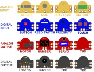
Style of Crumb
- Analog input: These Crumbs are coloured Yellow and provide a continuously varying input for the Crumble which can be read and used with the A. B, C and D connections
- Slider
- Dial
- Light Sensor
- Motion Sensor
- Digital input: Blue. These Crumbs provide a simple On/Off input to the Crumble controller. Again would be used with the A, B, C and D connections
- Button
- Magnetic Hall Effect Switch (previously Reed Switch)
- Proximity Sensor
- Dual Capacitive Touch Sensor
- PIR sensor
- Ultrasonic distance sensor
- Analog output: Red. These Crumbs allow the Crumble to continuously vary the device: speed of the motor, brightness of the Sparkles, Number shown on the display, position of the servo
- Motor
- Number Display
- Servo
- Digital output: Black. These Crumbs can be set either On or Off by the Crumble
Using Crumbs
Most Crumbs require a 5V Power and Ground connection to be made before they work fully. Sometimes this is to power the on-board electronics and sometimes, simply to ensure that the indicator LED works as expected.
The Crumbs are designed so that the Power and Ground (5V and 0V) can be applied to either the left or the right side. It doesn’t matter which you use. You can then use the opposite side to take the power to any other Crumb that you are using, as shown in the picture below:
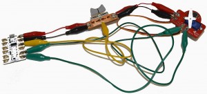
We recommend using short crocodile clips to join the Crumbs together as it reduces the amount of wiring considerably and the whole experiment becomes clearer to understand
Although the Crumbs are generally protected against connecting power on the wrong way round, or onto the wrong pin, it is recommended that you use some sort of colour coding so that the children can see how the positive power flows (using Red wires) or the negative with Black wires. You can use Green as an alternative to Black if you run out, but Yellow, White and Green are good colours to use for the general purpose inputs/outputs or motor outputs.
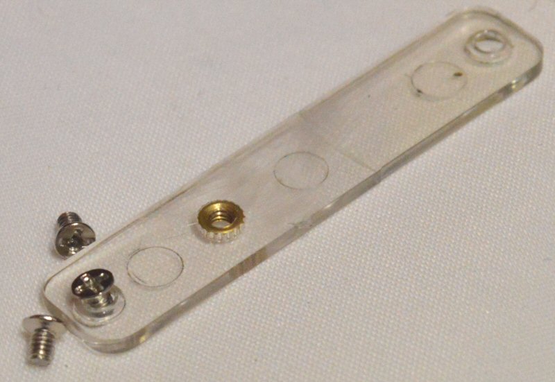
Where there are 2 crocodile lead connection pads next to each other on a Crumb (or indeed the Crumble) the two small holes that form part of the pads are designed to be exactly 5mm apart so that a standard 2-pin 5mm screw terminal can be soldered on. This allows you to use standard wires of exactly the correct length that are simply screwed into the terminal blocks as shown below:
Analog Input Crumbs (Yellow)
SLIDER

This requires Power and Ground to be connected and the output connected to A, B, C or D. The analog value read will be in the range 0 to 255, though in practice the power is not at 5V so the top end number will be lower
Sliding the slider to the left will give a value of 0, to the right will give the maximum number (probably 200 to 255)
The program below reads the value from the Slider Crumb connected to Input A, into the variable X. You can see the value being displayed on the left: x = 226

DIAL
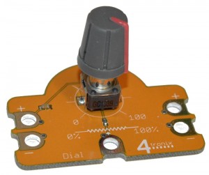
This requires Power and Ground to be connected and the output connected to A, B, C or D. The analog value read will be in the range 0 to 255, though in practice the power is not at 5V so the top end number will be lower
Turning the Dial anti-clockwise will give a value of 0, turning it clockwise will give the maximum number (probably 200 to 255)
The program below uses the value read from the Dial Crumb connected to Input A to set the speed of Motor 1. Note that the maximum value for motor speed is 100, so we divide the value from the Dial Crumb by 3 to be sure it fits into this range.

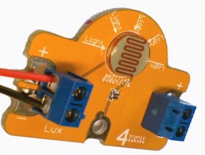
LUX/LIGHT
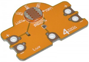
This requires Power and Ground to be connected and the output connected to A, B, C or D. The analog value read will be in the range 0 to 255, with 0 being total darkness and 255 being extremely bright.
Covering the light sensor completely will reduce to the minimum value and shining a bright light on it will achieve the maximum
The program below uses the value from the Light Sensor Crumb to set the brightness of the Red element of Sparkle 0. So in a dark room, the Sparkle won’t be as bright as in a bright room.

MOTION
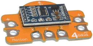
This requires Power and Ground to be connected and the outputs connected to A, B, C or D. The analog values read will be in the range 0 to approximately 125
You can tilt the board in X, Y or Z axis and the appropriate output will change its value. Maybe you can use this to steer a robot?
The program below extends the program for the Light Sensor Crumb by using all three axes of the Motion Sensor to set the three colour elements (Red, Green and Blue) of the Sparkle. So twisting and turning the Motion Crumb will change the brightness and colour of the Sparkle.

Digital Input Crumbs (Blue)
BUTTON
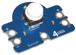
This requires the Power to be connected in order for the button to operate. In addition, you should connect the Ground so that the indicator LED operates.
When the button is not pressed, the output is 0 (Low) and the indicator is Off
When the button is pressed, the output is 1 (High) and the indicator is On
The program below starts Motor 1 running when the button is pressed and stops it when the button is released:

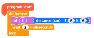
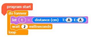
ULTRASONIC DISTANCE SENSOR
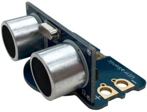
This requires the Power and Ground to be connected in order for the sensor to operate. You can connect the centre output to any of the 4 Crumble inputs (A, B, C or D).
Both the Trigger (T) and the Echo (E) are connected to the same pin, so use the same pin letter in both for the distance block.
Also, it is important that there is sufficient delay between repeated readings for the sensor to recover
The program below repeatedly reads a value and you can see it on the Crumble app by watching variable t:
MAGNETIC HALL EFFECT SWITCH
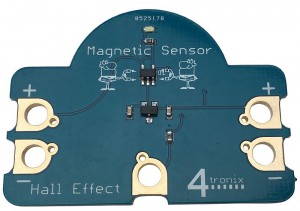
This requires the Power to be connected in order for the Hall Effect switch to operate. In addition, you should connect the Ground so that the indicator LED operates.
When a magnet is not present, the output is Low)and the indicator is Off
When a magnet (eg. a fridge magnet) is brought towards the sensor, the output is High and the indicator is On
The program below counts the number of pulses received from the Magnetic Switch Crumb. Maybe the magnet is on a wheel spinning round past the Crumb and this is counting the revolutions of the wheel?

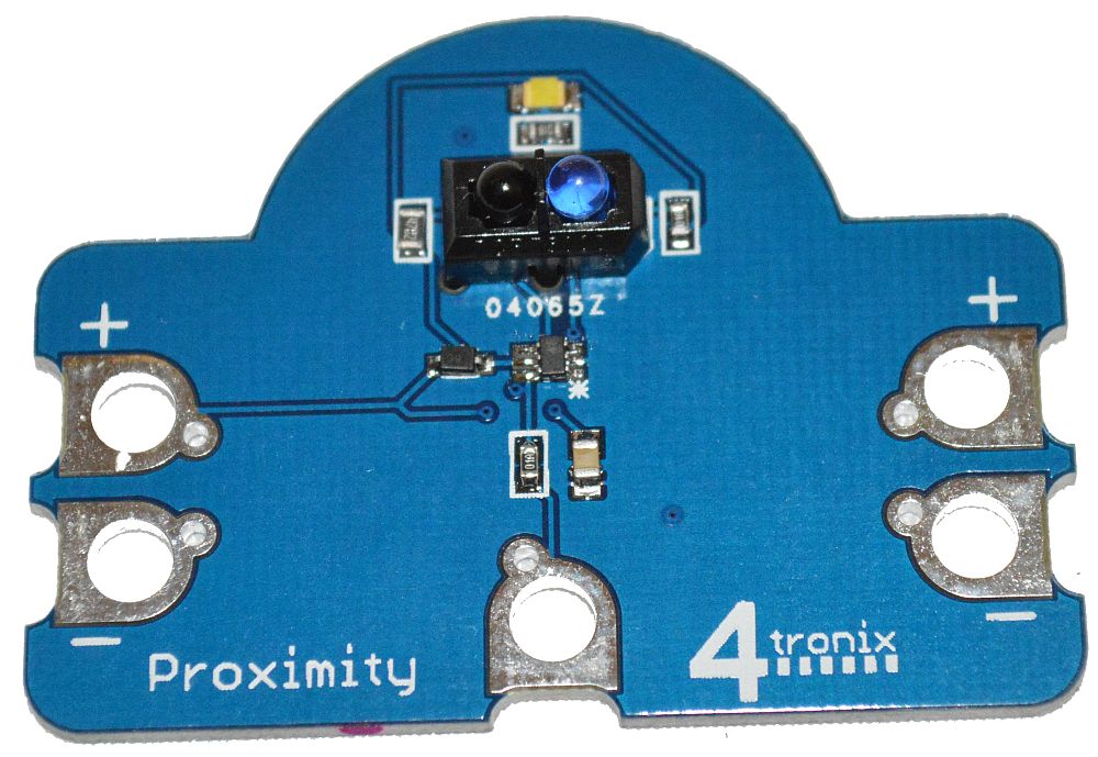
PROXIMITY SWITCH

This requires the Power and Ground to be connected in order to operate.
When there is no object near the sensor, the output is 0 (Low) and the indicator is Off
When an object (eg. a hand) is brought above the sensor, the output is 1 (High) and the indicator is On
The sensitivity is set such that a finger or hand would trigger it within about 2 to 3 cm. A reflective white card would be about 10cm
The following program waits for the trigger from the Proximity Crumb connected to input A then switches on the Buzzer connected to output B for 1 second

CAPACITIVE TOUCH SWITCH
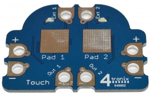
This requires the Power and Ground to be connected in order to operate.
When nothing is touching the sensor pads, the outputs are 0 (Low) and the indicator is Off
When a finger touches the sensor, the output is 1 (High) and the indicator is On
You can attach other objects such as pieces of fruit to the external inputs – give the system a minute or so to settle down (or remove and replace the power to reset it) after you change the connections
The program below uses the 2 outputs from the Touch Sensor Crumb connected to Inputs A and B to control 2 motors and steer a robot left or right

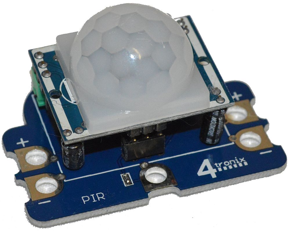
PIR (PASSIVE INFRARED) SENSOR
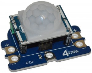
This requires the Power and Ground to be connected in order to operate.
When nothing moving is detected, the outputs are 0 (Low) and the indicator is Off
When movement is detected , the output is 1 (High) and the indicator is On
The program below flashes lights (on Output B) and Sounds a Buzzer (on Output C) when movement is detected

Digital Output Crumbs (Black)
TRAFFIC LIGHTS
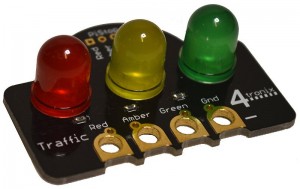
This requires the Ground to be connected and the Red, Amber and Green connections made to your choice of A, B, C or D on the Crumble
Setting the appropriate output on the Crumble to Hi will light the LED on the Crumb as well as the related LED on the Pi-Stop if one is plugged in
The following program runs a basic traffic light sequence with Red connected to A, Amber to B and Green to C

BUZZER
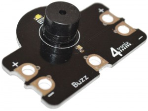
This requires the Ground and Power to be connected as well as the input connection made to A, B, C or D on the Crumble
Setting the output on the Crumble to Hi, will sound the Buzzer and light the indicator LED. Note that if the power isn’t connected, the indicator LED will still light, but the buzzer won’t sound.
The follow program plays a sort of Morse code SOS on the Buzzer Crumb connected to output A. (in fact it just does the first ‘S’ otherwise it would be a bit long)

Analog Output Crumbs (Red)
MOTOR
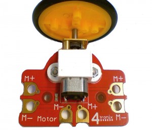
This requires the two terminals on the Crumb to be connected to the Motor1 or Motor2 outputs on the Crumble
There are 3 sets of the motor connector pairs. They are all identical, but make it easier to connect from different sides if for instance you use them to make a robot or similar
Setting the Motor Speed to 100 will turn the motor approximately 2 turns per second (120 rpm). The motor will stop turning if the speed setting is below about 20
If you connect + to + and – to – from Crumble to Motor Crumb, then FORWARDS = anticlockwise and REVERSE = clockwise.
The following program controls 2 motors to move a vehicle Forwards, Backwards, Spin Left, Spin Right and Stop continuously.

NUMBER
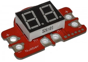
This requires Power and Ground to be connected as well as M+ and M- to be connected to the Motor1 or Motor2 outputs on the Crumble
Setting the motor speed to any number will cause that number to be shown on the display
Forwards is shown directly (eg “75”) but Reverse adds the decimal points so will show “7.5.”
See this blog entry for more information on using this Crumb
The program below simply counts up from -30 to +100 continuously:

SERVO
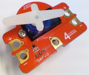
This requires Power and Ground to be connected as well as the centre connection to one of the outputs on the Crumble
Use the Servo command in the Crumble software to set the position of the servo
** Ensure that you do not try and set the servo outside the range of -90 to +90 or unpredicatble movements may occur
The following program uses the Slider or Dial Crumb connected to input A to adjust the position of the servo on Output B: