
Assembling Picobot 2
Picobot2 has been designed to be easily assembled by children armed only with a small screwdriver. As long as you are gentle with the acrylic layers there should be no problems in assembly.
If you find an acrylic layer is not fitting properly then either you have the wrong layer, or (layer 2 only) it is upside down.
Click on any photo to enlarge.
Step 1 – Check you have all the parts

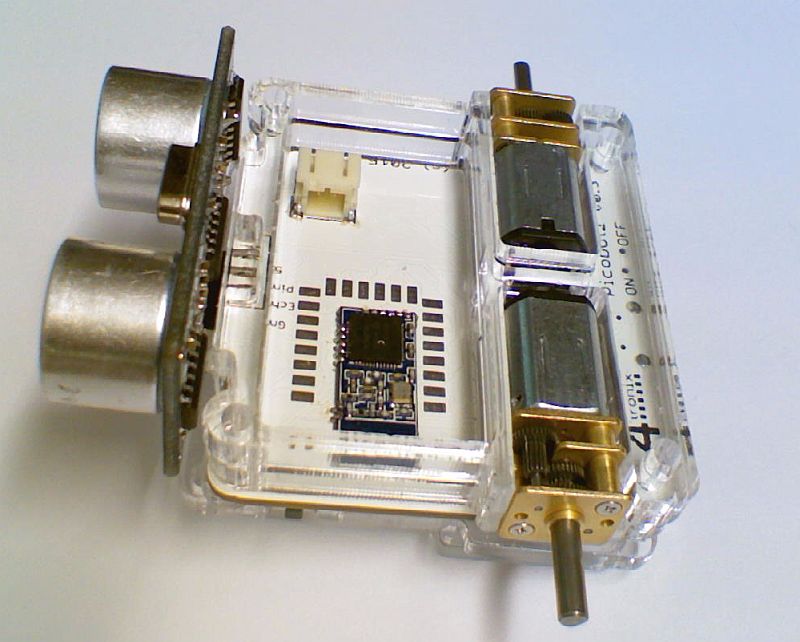
You should have (clockwise from top left):
- Picobot mainboard with ultrasonic and motors attached. Optionally, you may have a Bluetooth module (shown above) or an ESP8266 WiFi module
- LiPo battery (includes protection circuit and JST 2-pin 2mm connector)
- 2 wheels (Yellow or Lilac)
- 4 screws (M2.5, 22mm) and 4 nuts (M2.5)
- Layer 5 (top) acrylic. 2mm thick
- Layer 4 acrylic, 5mm
- Layer 3 acrylic, 5mm
- Layer 2 acrylic, 3mm (sits on component side of PCB)
- Layer 1 acrylic, 3mm (Bottom – with front glider attached)
Step 2 – Place Layer 2 onto the PCB

Note that this layer only goes one way round as it weaves in and out of the components on the PCB.
This layer is quite fragile until it is assembled, do not bend it!
Step 3 – Place Layer 1 onto Layer 2

Layer contains the hemi-spherical glider, which acts as the front caster for the Picobot2
Step 4 – Turn over and Place Layer 3 Between the Motors

Layer 3 and Layer 4 are quite similar and both are 5mm thick. Layer 3 has a small cutout at the centre front where the ultrasonic module is mounted.
Step 5 – Add Layer 4 above Layer 3
This also fits between the motors and the top of this layer should be flush with the top of the motors
Step 5 – Plug in the Battery

Plug in the battery onto the main PCB then position it carefully into its cavity making sure that the antenna end (left side) of the Bluetooth or ESP8266 module is not covered by the battery
Step 6 – Add the Top Layer (Layer 5)

This top layer holds in the battery and the motors
Step 7 – Screw it all together

Do up all 4 screws. with the screw head at the top and the nut underneath the Picobot2. They don’t need to be done up very tightly, just tightening by hand is sufficient
Step 8 – Finally, push the wheel on

Put each wheel flat on the table and push the axle through the wheel until it is stopped by the table. The axle end should be flush with the outside of the wheel
You now have a fully functional (optionally WiFi or Bluetooth enabled) mini robot to program away with!