Ultrasonic CrumbleBot Addons


Download Updated Crumble software from here
This post gives brief instructions for assembling the Static and Panning versions of the Ultrasonic addon for CrumbleBot
You will need version 25.5 or later of the Crumble Software – see the link above to download it.
Static Ultrasonic Distance Sensor
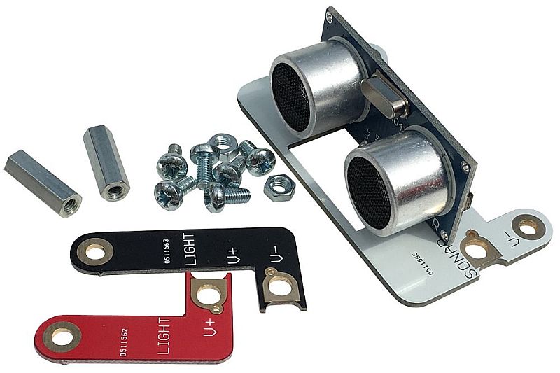
Check you have the correct parts:
- White base PCB with ultrasonic sensor
- Red Positive power connection PCB
- Black Negative power connection PCB
- 2 x 15mm Pillars
- 6 x 6mm Screws
- 2 x Nuts
Fit the Distance Sensor to the CrumbleBot
- The Black negative power connector PCB is fitted on the left side of the CrumbleBot with the writing facing upwards.
- Use a screw and nut to screw the connector PCB into the hole marked V-. Do not tighten the screw
- Screw in the Red positive power connector PCB onto the right side of the CrumbleBot using a screw and nut into the connector marked V+. Don’t tighten the screw.
- The other ends of the two power connectors PCBs should line up with the 2 mounting holes at the front of the CrumbleBot
- Now use 2 more screws to fit the 15mm pillars onto the top side of the CrumbleBot, feeding the screws through the mounting holes, through the power connector PCBs and into the pillars
- Finally, use the 2 remaining screws to fit the main ultrasonic sensor board to the tops of the 2 pillars
- Now tighten all the screws so everything is fixed tightly
- It should now look like the photo below
Using the Static Distance Sensor
- Ensure you have downloaded the latest version of the Crumble Software (must be at least v25.2)
- Use a crocodile clip cable to connect one of the inputs (A, B, C or D) to the connection marked “SONIC” on the sensor board
- Use the “Distance” block and set both ‘T’ and ‘E’ to the same pin as you are using to connect the sensor (The example below shows it connected to input A)
- The example code below simply gets the distance and saves it into variable t. You can look at the variables and see the distance change as you move your hand in front of the sensor

Panning Ultrasonic Distance Sensor

Check you have the correct parts:
- White base PCB with ultrasonic sensor and 4-pin connector
- Larger White PCB with servo and 4-pin connector
- Red Positive power connection PCB
- Black Negative power connection PCB
- 2 x 25mm Pillars
- 6 x 6mm Screws
- 2 x Nuts
- 4-way Female-Female 10cm Cable (various colours)
Fit the Distance Sensor to the CrumbleBot
- The Black negative power connector PCB is fitted on the left side of the CrumbleBot with the writing facing upwards.
- Use a screw and nut to screw the connector PCB into the hole marked V-. Do not tighten the screw
- Screw in the Red positive power connector PCB onto the right side of the CrumbleBot using a screw and nut into the connector marked V+. Don’t tighten the screw.
- The other ends of the two power connectors PCBs should line up with the 2 mounting holes at the front of the CrumbleBot
- Now use 2 more screws to fit the 25mm pillars onto the top side of the CrumbleBot, feeding the screws through the mounting holes, through the power connector PCBs and into the pillars
- Then use the 2 remaining screws to fit the servo board to the tops of the 2 pillars
- Now tighten all the screws so everything is fixed tightly
- Push the Board containing the ultrasonic sensor onto the top of the servo and use the screw inside the servo parts bag to fit it more permanently (actually, you can leave this off until you are sure you have it set to the centre position when the servo is centred)
- Finally, use the 4-way cable to connect the Sensor PCB to the Servo PCB. Make sure that the wires do not cross over. So for example, if you have Brown, Red, Yellow Orange at the top, then you must also have Brown, Red, Yellow, Orange at the bottom. (your wires may be completely different colours, so just ensure they are in the same order at the top as at the bottom)
- You should now have something like the photo shown below
Using the Panning Distance Sensor
- Ensure you have downloaded the latest version of the Crumble Software (must be at least v25.2)
- Use a crocodile clip cable to connect one of the inputs (A, B, C or D) to the connection marked SONIC on the servo board
- Use another crocodile clip cable to connect one of the inputs to the connection marked SERVO on the servo board
- Use the “Distance” block and set both ‘T’ and ‘E’ to the same pin as you are using to connect the sensor (The example below shows it connected to input A)
- Use the “Servo” block to set the position of the servo from -90 degrees to +90 degrees. 0 degrees should be straight ahead
- The example code below sets the servo to straight ahead, then gets the distance and saves it into variable t
- If the servo is not pointing straight ahead, pull off the top PCB with the sensor on and fit it onto the servo again so it is pointing ahead. Then tighten the screw.
