Wheel Encoders on Pi2Go-Lite
You can also download a PDF of this guide from here
These simple encoders provide 16 pulses per revolution of the main wheels and allow you to program your vehicle to:
- Travel in straight lines, even if the motors naturally move at slightly different speeds
- Travel a fixed distance
- Turn a set angle
The Pi2Go-Lite is already able to take the sensors. Both the Python library and ScratchGPIO incorporates the sensors and allows you to easily write your own programs to use them as you wish.
The encoder/sensors are supplied as a kit and require some soldering to complete.
Fitting the Encoder Sensors
Step 1: Identify the parts
** NB. Please check you have the correct resistors in the pack BEFORE soldering. We think there may be a few wheel sensor packs with incorrect resistors, so please double check first as it is much easier to resolve the problem before soldering. Specifically the 10K resistors may be incorrect, check they have Brown, Black and Orange stripes
Note: Check which Pi2Go-Lite main PCB you have as the instructions are slightly different
- v1.0: The selection jumpers are not included with v1.0 and a cut needs to be made on a solder jumper to enable wheel sensors
- v1.1: The selection jumpers and header is included with the base kit, so not separately required for the wheel sensor kit
- v1.2: The base kit includes a slide switch to select line follower or wheel sensors, so not required in the wheel sensor kit
- 2 x encoder discs (if this pack was ordered at same time as the Pi2Go-Lite, the discs will already be fitted to the wheels)
- 2 x IR reflectance sensors
- 2 x resistors 10K (Brown, Black, Orange)
- 2 x resistors 220R (Red, Red, Brown)
- 3×2 male jumper block: Not required for v1.1 and above
- 2 x 0.1″ jumpers: Not required for v1.1 and above
Step 2: Attach the Wheel Encoder Discs
I prefer to use 5 drops of superglue – one on each spoke of the wheel. Then drop the encoder disc into each wheel as shown, with the black/white markings uppermost. Leave to dry while you get on with the soldering.
If you prefer, you can also use double-sided adhesive pads
Ff the wheel sensor pack was ordered at same time as the Pi2Go-Lite, the discs will already be fitted to the wheels
Step 3: Cut the Selector Tracks – v1.0 ONLY
** This step is only required for v1.0 PCBs
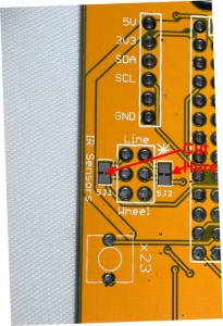
On the left of the Pi2Go-Lite is an empty position for the 3×2 male header block. To each side of that is a pre-linked solder jumper – click on the image above to enlarge and clarify. You need to cut these links carefully using a sharp craft knife. Be careful not to cut anything else!
When these links are cut and the jumper block added, then you can select whether to use line-follower sensors or wheel sensors. There are not sufficient available GPIO pins on the 26-0pin connector for both to be in operation at once.
Step 4: Add the IR Sensors
As when building the Pi2Go-Lite kit originally, you should cut the pins on the sensors, next to the flattened part on the legs. Then solder them on.
NB. The Blue LED for the left sensor is at the front, but the blue LED for the Right sensor is at the rear. Use the silk screen angles to identify.
Snip the plastic legs/fixings off the sensors, or these will impeded the mounting of the motors.
Step 5: Add the 10K Resistors (Brown, Black, Orange) – v1.0 Only ***
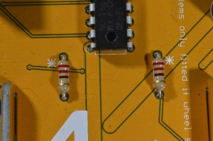
As shown in the image above, these need to be connected directly to the sensors on the top of the board.
Bend the legs on each resistor and cut off all but 4mm of the legs, then solder on carefully
Step 6: Add the 220R Resistors (Red, Red, Brown)
These can be soldered into the middle of the board in positions marked with an asterisk.
** For v1.1 PCBs and above, also fit the 10K resistors (Brown, Black, Orange) to the positions next to the 220R resistors
Step 7: Add the Jumper Block – v1.0 Only
** v1.0 only Ensure you have cut the 2 tracks as described in step 3. It is really difficult to cut the tracks after the jumper block is fitted.
Now solder on the 3×2 male jumper block.
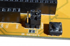
Important Info: The jumpers (or switch for v1.2 and above) can be placed in one of 2 positions:
- Front: Use the line follower sensors
- Rear: Use wheel sensors
The wheel sensors are now ready to go.


