MicRoCon Robotics Controller Kit

Click on any image to enlarge.
The MicRoCon is the baby sister to the more powerful PiRoCon board, but incorporates many of the same features and in fact can use exactly the same code for programming as the pins it shares are the same. Here is a brief comparison table between the controllers:

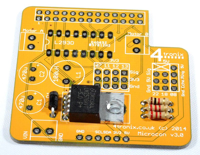
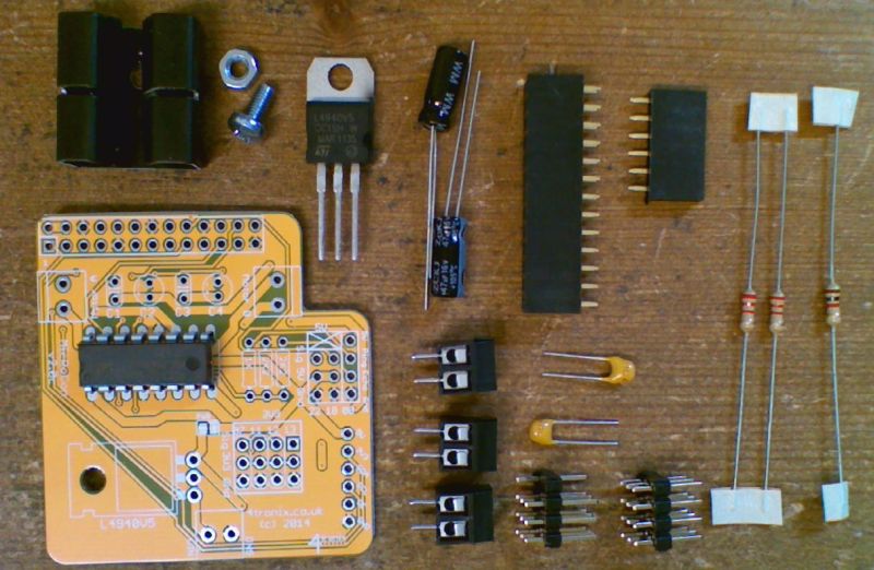
Check you Have all the Parts

- Printed Circuit Board (PCB) with the 5V regulator already fitted
- L293D H-Bridge driver chip
- 470uF capacitors x 2
- 100uH Inductor
- Diode
- 2-pin Screw Terminals x 3
- 2K2 resistors x 2 (coded Red-Red-Red-Gold)
- 1K resistor (coded Brown-Black-Red-Gold)
- 4×3 male header blocks x2 (one has 2 pins removed) [alternatively we may ship with 4 off 2×3 male header blocks depending on availability]
- 6-pin female header
- 26-pin GPIO header
- Fixing hardware – M3 screw, M3 nut
- Heatsink
- Rubber “foot”
Starting Soldering
If you haven’t soldered before, you might want to check out this instructable. I find that the following order of soldering works best, starting with the lowest profile components and moving to the highest. This allows me to place the components through the holes in the PCB, then turn the PCB over onto the desk surface and gravity will hold the components in place. You can also use Blutack to hold the components in place while you solder
1. Add the Resistors
The PCB is labelled with the resistor values. 2K2 resistors are marked by Red-Red-Red-Gold bands, and the 1K resistors is Brown-Black-Red-Gold. It is neatest to ensure that all resistors point the same way. Make sure you snip off the leads on the back after soldering.

2. Add the Diode
The PCB is labelled with the resistor values. 2K2 resistors are marked by Red-Red-Red-Gold bands, and the 1K resistors is Brown-Black-Red-Gold. It is neatest to ensure that all resistors point the same way. Make sure you snip off the leads on the back after soldering.
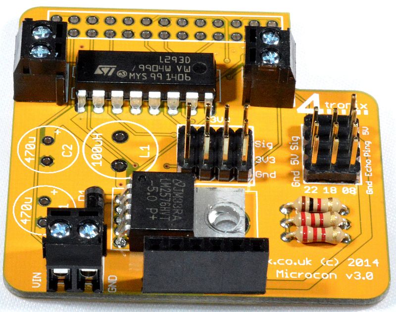
3. Add the L293D chip
Make sure that pin 1, marked by the little black round indentation and the U-shaped cutout of the chip, is at the edge of the board as shown below.
Note: This chip may already be inserted in the board for protection during transport – but it won’t be soldered.

4. Add the screw terminals
These terminals are used to connect the motors and also to supply external power to the board for the regulator and the motor driver.
Solder all the terminals onto the PCB facing outwards

5. Add the Male Header blocks
These 4×3 header blocks are slightly different from each other, as one has 2 pins removed from it. Make sure you put them into the correct place as they would be difficult to remove if placed incorrectly (of course the block with all its pins won’t fit into the other position, but vice versa is possible).

7. Add the 6-Pin Female Header
This header brings out the I2C pins from the Raspberry Pi together with 5V, 3.3V and Ground. This is our standard layout and the 4tronix IP Display dongle will fit directly in here.
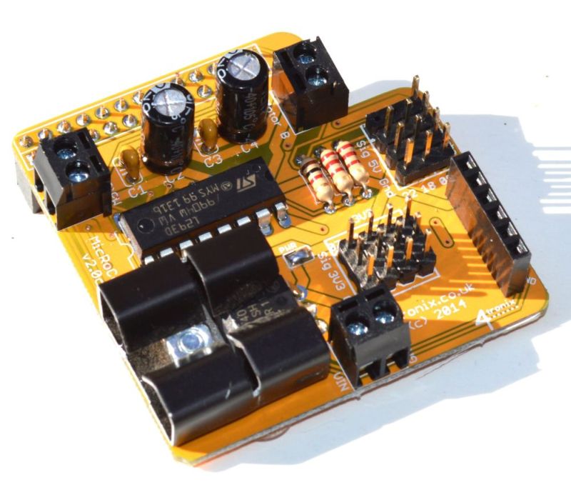
8. Add the 470uF Capacitors C1 and C2
These are polarised and must be placed the correct way or magic smoke will appear. The long lead is positive and should be placed in the hole marked with a ‘+’ on the PCB. The casing has a grey band with down arrows next to the negative pin – the grey band should be facing the GPIO connector as shown below. Cut off the legs on the underside after soldering

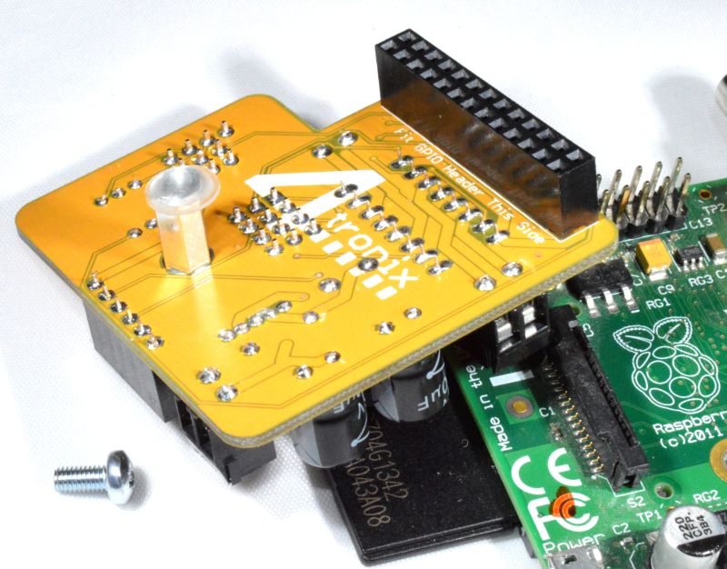
9. Solder the GPIO Connector to Bottom of PCB
Your kit may be provided with a choice of standard or extended header – select the one you want to use. The other is not required. Make sure you solder this to the correct side of the board!

11. Finally Fit the Pillar and rubber foot, then fit onto the Raspberry Pi


Return to MicRoCon Home