Tour of PiRoCon
In this post we will take a tour around the PiRoCon v2 board and see how all the various elements operate and can be configured

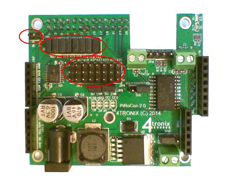
Power Supply

- The DC Jack (bottom left) is the input connection for your battery voltage. The voltage should be between 7V and 12V and will need to be able to supply at least 2A. This is a 2.1mm DC Jack with positive centre pin. Below about 6.5V, the regulator will not be able to output the 5V required for the Raspberry Pi to work. Above 12V, the regulator will probably get too hot.
- The voltage regulator (lower left side) is used to convert the input voltage to 5V as required by the Raspberry Pi. For version 2 of PiRoCon we use a switching regulator which barely gets warm even at higher input voltages and no heatsink is required. Note that the motors are not powered from the regulated power supply
Motor Drivers

- The terminals for two DC motors are at the top right of the board. Motor A on the left and Motor B on the right
- Both terminals are wired the same way (left to right) so the same inputs would drive the motors in the same direction. If you use one motor for a left side drive on a robot and the other for a right side drive, then you should swap the wiring for the second motor. For instance, using the example programs on the Initio, you should wire Red-Black-Black-Red
- The motor terminals are driven directly from the output of the H-Bridge driver chip L293DD (shown just below the motor terminals)
- The 4 GPIO pins used to drive the chip are the SPI pins CE0, CE1, MISO and MOSI. These are connected via solder jumpers (to left of the L293D) – these are pins 19, 21, 24, 26
- If you want to use other pins to drive the motors, then you should cut these these connections and wire your own connections to the required positions
- Each motor has an enable pin which by default is connected directly to 5V using the jumpers just above the solder jumpers and below the 8×3 header block. For some purposes it is better to use the enable pins for the PWM signal, so that you can use the 4 control pins to purely control the direction. If you want to do that, then you should remove the jumpers and wire the enable pins to a PWM source (eg. an Adafruit 16-channel PWM board plugged into the PiRoCon expansion sockets)
- In the bottom right of the photo above is a separate 2-pin terminal for external power. If you don’t want to drive the motors from the incoming battery voltage on the DC jack, you can move the selection jumper (just above the 2-pin terminal) and provide your motor voltage directly to the 2-pin terminal. This voltage can be from 5V-15V DC – ensure you connect it the correct way round. Note that this 2-pin terminal does NOT power the 5V regulator, only the motors.
- For normal operation using the DC jack input. ensure the jumper is placed to the right side, or no power will get to the motors
5V GPIO Connector (8×3 rows)
- NOTE: The Ground pin for the 8×3 block of GPIO pins is at the lower side for v2 PiRoCon (upper side for v1), so be careful when wiring
- There are 8 unallocated GPIO pins available and these are brought out to a bank of 8×3 male headers
- The headers are at 0.1″ pitch so you can connect standard 3-pin 5V sensors or servos etc. directly to them
- Each signal is separately fed through a bidirectional level converter so can safely be used to input or output at 5V
- Each signal is labelled with an x-number (on the jumper block) and a #-number
- x refers to the physical pin number on the GPIO connector. So the first signal on the left is x07 which is pin 7 on the GPIO connector
- # refers to the GPIO number itself. So the first signal (x07) is GPIO#04
- Each signal can be disconnected from the GPIO header to the Raspberry Pi, by removing the relevant 2-pin jumper (shown top left)
- If you remove the jumper, then the related signal in the bank of 8×3 is no longer in use
- You should then connect a 3.3v max input or output to the signal pin where the jumper was
- This allows the use of 3.3V sensors (eg. the wheels sensors on the Initio)
- There is a 2-pin header (top left) which has two 3.3V connections, intended for powering 3.3V sensors
- #04 – x07
- #17 – x11
- #18 – x12
- #27 – x13
- #23 – x16 NB. Labelled incorrectly on board as #22
- #22 – x15 NB. Labelled incorrectly on board as #23
- #24 – x18
- #25 – x22
Please note, as described above, there is a layout mistake on the PCB which results in pins 15 and 16 (GPIO numbers 22 and 23) being swapped. So ensure that you plug into the correct connection for your application
Ultrasonic Sensor

- There is a group of 4 pins (shown above at top right) that are designed to add an HC-SR04 ultrasonic sensor directly to
- From the left, these are 5V, Trig, Echo, Gnd and match the ordering of the pins on the sensor
- There are 3 resistors which process the signals so that both Trigger and Echo can use the same GPIO pin on the Raspberry Pi and also that this is 3.3V safe
- The jumper (just below and left of the ultrasonic 4-pin connector) can be used to select either TXD (pin 8) or SCLK (pin 23)
- If you want to use a completely different pin, simply remove the jumper completely and connect the pin you want to use to the centre pin of these 3
SPI Connector

This 8-pin female header allows you to connect the SPI signals. Note however that these are also used for motor controls by default, so you may need to attach the motors to different pins if you want to use SPI. Alternatively, simply don’t connect the motors when using SPI.
- 5V
- 3.3V
- CE1
- CE0
- SCLK
- MISO
- MOSI
- GND
I2C Connector

This 6-pin female header allows you to connect additional modules using the I2C connections. These are not used on the PiRoCon itself, although the expansion boards (see below) can use them. This connector also has the UART RXD/TXD pins on together with Gnd and 3.3V
- Gnd
- RXD
- TXD
- SDA
- SCL
- 3.3V
Expansion Board Sockets

There are two 6-pin expansions sockets that use I2C connections to add functionality to the PiRoCon. Expansion boards available right now are:
- 4-channel analog input (ADC) with single channel analog output (DAC) from 4tronix

- 16-channel PWM or servo driver from Adafruit

If you use stacking headers for the 6-pin connectors, and right-angle headers for the signals on the boards, you can stack these I2C expansion boards as much as you like. Here are both the above expansion boards fitted:
