Drive:Bit Motor Controller
Purchase Drive:Bit here
Drive:Bit has been created to provide a really affordable motor and robotics controller board for the BBC micro:bit. Even though we reduced the price as much as we could, we kept some great features which will make it an excellent board to build DIY buggies and the like
Connections
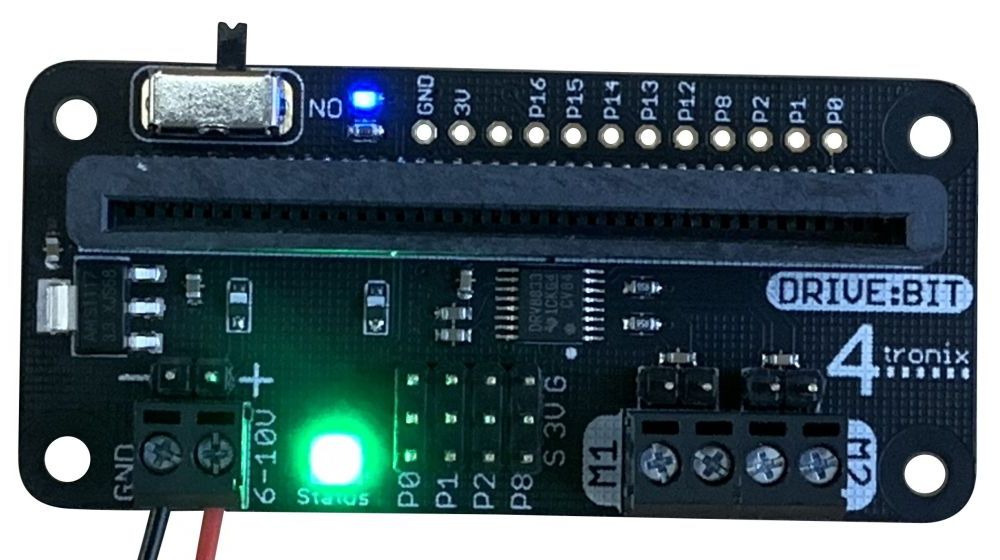
NB: Fit the Microbit into the connector with the LEDs on the Microbit facing the switch and indicator LED.
Connect your batteries to the 2-pin screw terminal, or the 2-pin header pins, on the left. The battery voltage should be in the range 6V to 10V, so use 4 x AA alkaline cells, or a 9V PP3 battery or similar. This input voltage is what is used to drive the motors and generate the 3.3V for the Microbit, so make sure that your motors can cope with the voltage you provide and that the voltage is kept high enough when the motors take a lot of current.
Connect your motors to the 2-pin screw terminals (or 2-pin male headers). Motor 1 is on the left, labelled M1. Motor 2 is on the right, labelled M2. The current to the motors is limited by the circuitry so it won’t damage the DriveBit if you try and take too much current. However, if things aren’t working, switch off and check for short circuits. Better safe than sorry!
In the centre of the DriveBit is a group of pins, 4 x 3. These are GVS (Ground, Voltage, Signal) pins that allow you to connect 3.3V devices (inputs or outputs) directly to the Microbit pins 0, 1, 2 and 8. Small, micro, servos such as SG90 can be plugged in directly – although they are 5V devices they will generally work at 3.3V.
Other pins are available on the top of the board as pads. You will have to solder wires in there, or you could add a (male or female) header yourself.
Programming Drive:Bit with Makecode
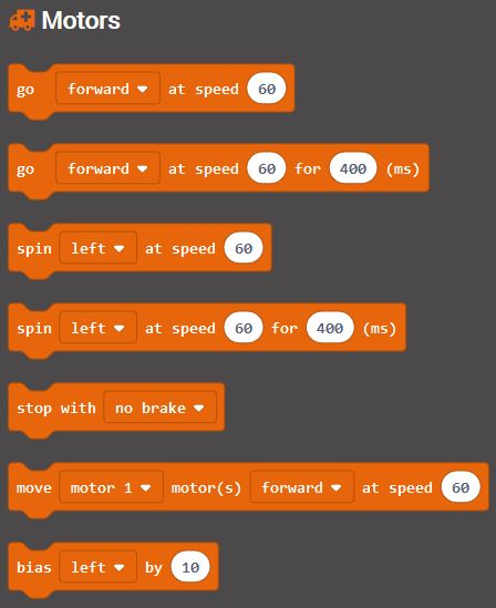
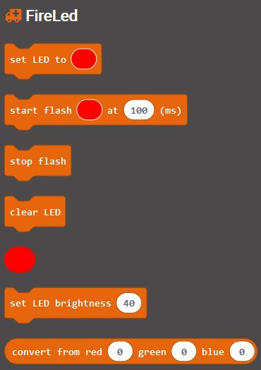
There is a Makecode extension available which makes it trivial to control the motors or set the status FireLed to any colour with or without flashing. The 4 GVS pins are general purpose so use other Makecode libraries to drive what you connect to these pins.
In Makecode editor go to Advanced and Extensions, then search for DriveBit
Driving Motors:
Setting the Status LED
Using Drive:Bit with MicroPython
For micro Python, you can drive the motors and the onboard status LED very simply. The pins used are:
Motor 1: Pin 12 and Pin 13
Motor 2: Pin 14 and Pin 15
LED: Pin 16
To drive forward, Set Pin 12 and Pin 14 to the speed you want, from 0 to 1023. And set Pin 13 and Pin 15 to 0. Eg. to drive at speed 600
pin12.write_analog (600)
pin13.write_analog (0)
pin14.write_analog (600)
pin15.write_analog (0)
To drive backwards, set Pin 12 and Pin 14 to zero, and set Pin 13 and Pin 15 to the speed you want, from 0 to 1023. eg to reverse at speed 600
pin12.write_analog (0)
pin13.write_analog (600)
pin14.write_analog (0)
pin15.write_analog (600)
To stop the motors, set both pins of each motor to 0. This will coast to a stop
pin12.write_analog (0)
pin13.write_analog (0)
pin14.write_analog (0)
pin15.write_analog (0)
To brake the motors quickly, set both to 1023
pin12.write_analog (1023)
pin13.write_analog (1023)
pin14.write_analog (1023)
pin15.write_analog (1023)
To drive the LED, you will need to import and use the neopixel library. This example sets the LED to Red
import neopixel
np = neopixel.NeoPixel(pin16, 1)
np[0] = (255, 0, 0)
np.show()
- Line 1 imports the neopixel library
- Line 2 sets up the array of LEDs that the library will use. We only have 1 LED
- Line 3 sets element 0 (our only LED) to Red=255, Green=0, Blue=0
- Line 4 copies the array of LED data to the LED itself