MiniBit Entry-Level Robot for Microbit
Purchase here
Overview
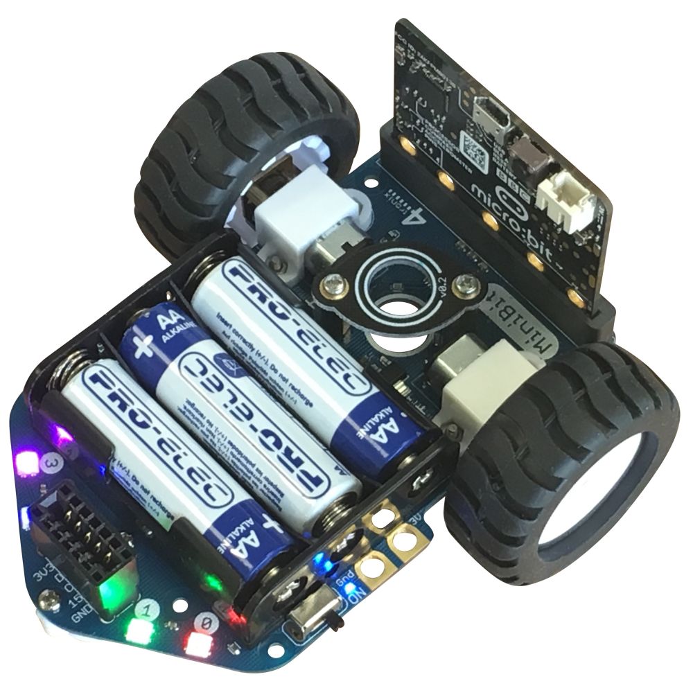
MiniBit is a ready-assembled simple and inexpensive robot for the BBC micro:bit.
It has the following features:
- Ready-assembled. Just push on the wheels
- Edge connector to easily insert the Microbit
- Micro metal gear motors with fully-enclosed gearbox (no grit or fluff can enter)
- Wire-free battery holder for 3 x AA batteries
- 4 x Smart RGB LEDs (neopixel compatible)
- Integrated Pen holder for 10mm diameter pens (eg. Sharpie felt tips)
- Robust On/Off switch with Blue indicator LED
- Wide chunky wheels with lots of grip
- Metal ball front caster
- Connector for optional ultrasonic sensor or I2C breakouts (fully compatible with Pimoroni’s Breakout Garden range)
- The Microbit pins 0, 1, 2, Gnd and 3V are available for use with croc clips etc.
- Lots of mounting holes to create your own “body” for the robot or additional sensors etc.
- Makecode extension and micropython examples available
Batteries
Please use Alkaline batteries. Rechargeable batteries do not provide sufficient voltage once they have started to deplete. This primarily affects the ultrasonic sensor, so you may be okay to use with the other functions even when the batteries get low
Coding Your MiniBit
Calibrating the Motors (v1.3 or later Only)
For version 1.3 of Minibit we have added code and hardware to help calibrate the motors on either side so that they match speeds better. Once the motors are calibrated, the calibration values are permanently remembered on the Minibit, so even using different Microbits and different programs, you will still get the matched motors. For this to work you must use the latest Minibit Makecode extension.
The calibration Makecode program can be downloaded from >here<. Load it into your Makecode editor and download to the Microbit on the Minibit v1.3 or later.
Process: The calibration program starts at speed 30 (displaying 3 on the Microbit LEDs). You then set the left or right speeds until it is driving straight. Then give the Minibit a good shake and it will change to speed 60 (displaying 6). Set this speed, shake again to change to speed 90 (displaying 9). Once this speed is set correctly, shake again and it will return to speed 30. You can then switch off and all the values are stored. If you run the program again, you will start from the un-calibrated values and must follow all the steps again.
- Load the program into the Microbit and plug it into the Minibit
- Switch on the Minibit. It will display 13 (indicating a v1.3 Minibit), then change to show 3 (meaning speed 30)
- Press A or B buttons to affect the turning left or right, then press both A+B simultaneously and the Microbit will display the current calibration value, then move forward for 2 seconds at speed 30.
- If it is still not moving straight, press the appropriate button one or more times to straighten it up, then press A+B again to test it
- When you’re happy that it is moving straight, give the Minibit a shake and it will store the values for speed 30 and move onto Speed 60.
- Repeat for speed 60 and speed 90
Microsoft MakeCode
Click any image to enlarge.
To load the extension, select Advanced, then Extensions. Then enter “Minibit” into the search box and press Enter. If that doesn’t find it (there are sometimes earch glitches) you can enter the full URL into the search box: “https://github.com/4tronix/MiniBit”
NB. This post is being updated to relate to the new functions added (Feb 2020). Images may not match the text.
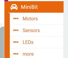
Once loaded, you will have a MiniBit menu item with 4 sub-folders: Motors, FireLeds, Sensors, Addons
Motor Blocks
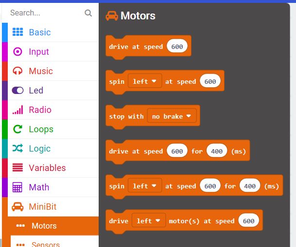
The “New style block” section contains command for basic movements eg. “Go Forwards/Reverse at speed 60” or “Rotate Left/Right at speed 40 for 700 ms”. All the commands in this section use speeds from 0 to 100 inclusive.
Both the “Go” and the “Rotate” blocks have a paired block that will do the command for a selected amount of time and then stop
There are two ways of stopping. Coasting to a stop or braking. If you set the speed to 0 or use the “stop with no brake” command, then it will stop gently over the coourse of a second or so depending on initial speed). If you use the “stop with brake” block (or the go/rotate for a time block) then it will stop almost immediately.
You can also drive each motor individually using the “Move Left/Right/Both motors…” block. For instance if you set the left motor to drive at 600 and the right motor to drive at 1000, then it will perform an arc towards the left
We have introduced a new command to bias the driving in one direction or the other. This is to counteract any mismatch between the motors. So if your robot drifts over the left when you want it to go straight, then add a bias to the Right. At a speed of 60, a bias of 10% is roughly equal to 10 cms or so.
FireLed Blocks

You can use these blocks to set and clear one or all the FireLeds.
Using the “Enable Bluetooth” block at the top level you can disable the Fireleds. The Bluetooth software for Microbit is not compatible with Fireleds (like neopixels and all such LEDs) so you should switch off the Fireleds using this block if you want to use the Microbit Bluetooth functionality.
Note that the MiniBit defaults to automatically updating the FireLeds whenever any change is made, but you can change this behaviour by setting the update mode to manual. Then you would have to run the “Show LED changes” block after making any changes to the LED settings.
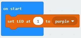
The LEDs on the MiniBit are labelled from 0 to 3. Use these numbers in the Makecode blocks to change the colour. eg setting LED 1 to Purple could be done like this:
The default brightness level is 40. This is plenty bright enough for most uses, saves damaging eyes, and reduces battery consumption. If required you can change the brightness from 0 up to 255
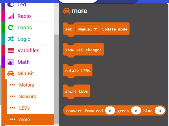
In the Advanced section of FireLeds :
Set update mode is used to switch between automatic LED updates or manual LED updates. The default is for automatic updates: every change to the LEDs results in all the LEDs being written to with the updated values. This is easy to understand, but it does mean that when making a lot of changes it can slow things down considerably. If doing that, it is best to use Manual update mode, make all the changes required, then use the show LED changes block to make all the updates in one go.
Rotate LEDs block will move the colour in LED 0 to LED 1, LED1 to LED2, LED2 to LED3 and LED3 to LED0. If done repeatedly, with a delay between each one, it will show the LED colours rotating around all the 4 LEDs.
Shift LEDs block will move LED0 to LED1, LED1 to LED2 and LED2 to LED3. It will blank LED0. So all the colours will disappear one at a time from 0 to 3
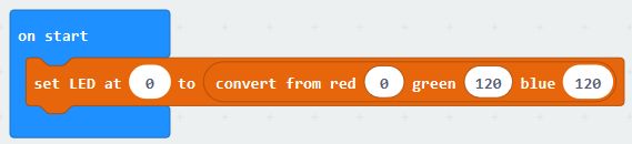
You can also create your own colours and replace the fixed list of colours in any command using the convert from red, green, blue block. For example, to set LED0 to a blue-green colour:
Sensor Blocks

Ultrasonic distance sensor: You can get the values to the nearest object in cm, inches or microseconds. This block returns a number that you can put into a variable or use it directly in a calculation or test
Line sensors: This optional accessory has 3 sensors: left, centre and right. These are connected directly to Pin 0, 1 and 2 of the Microbit. There are two ways of using the sensors: a) read the current value and check it’s state before deciding what to do, or b) use a block that only gets run when the requested event occurs. eg: when the left sensor finds a (black) line
More Blocks
These are the advanced usage blocks. Most students will not need to use them.
- Set update mode is used to switch between automatic LED updates or manual LED updates. The default is for automatic updates: every change to the LEDs results in all the LEDs being written to with the updated values. This is easy to understand, but it does mean that when making a lot of changes it can slow things down considerably. If doing that, it is best to use Manual update mode, make all the changes required, then use the show LED changes block to make all the updates in one go.
- Rotate LEDs block will move the colour in LED 0 to LED 1, LED1 to LED2, LED2 to LED3 and LED3 to LED0. If done repeatedly, with a delay between each one, it will show the lED colours rotating around all the 4 LEDs.
- Shift LEDs block will move LED0 to LED1, LED1 to LED2 and LED2 to LED3. It will blank LED0. So all the colours will disappear one at a time from 0 to 3
- You can also create your own colours and replace the fixed list of colours in any command using the convert from red, green, blue block. For example, to set LED0 to a blue-green colour:
Programming in microPython
Driving Motors
The motors use 2 pins each to determine the speed and direction. In microPython we use write_analog ( ) to set the first pin to a value between 0 and 1023 and the second pin to 0 in order to go forward. To reverse, we swap the pins so that the first pin is set to 0 and the second pin is set to the value.
On the MiniBit the left motor uses pins 12 and 8, and the right motor uses pins 16 and 14.
So to move the left motor forwards at speed 600:
pin12.write_analog(600)
pin8.write_digital(0)
And to move the right motor in reverse at speed 450:
pin16.write_digital(0)
pin14.write_analog(450)
To stop with no brake, use write_digital ( ) to set both pins to 0. To stop with brake, set both pins to 1.
eg. stop left motor with coasting and right motor with brake:
pin12.write_digital(0)
pin8.write_digital(0)
pin16.write_digital(1)
pin14.write_digital(1)
So a complete, but fairly useless, program to drive the motors for 2 seconds and then stop quickly, would look like this:
from microbit import *
pin12.write_analog(600)
pin8.write_digital(0)
pin16.write_analog(600)
pin14.write_digital(0)
sleep(2000)
pin12.write_analog(0) # temporary fix for python bug
pin12.write_digital(1)
pin8.write_digital(1)
pin16.write_analog(0) # temporary fix for python bug
pin16.write_digital(1)
pin14.write_digital(1)
Note the 2 lines that write_analog(0) before swapping a pin from analog to digital. These are required until a fix is obtained for the python PWM driver continually updating the pin type to analog
Lighting the LEDs
This uses the standard neopixel code, with the LEDs connected to Pin 13.
At the top of your program add import neopixel then:
leds = neopixel.NeoPixel(13, 4)
leds is then an array of all 4 LEDs. leds[0] refers to the LED 0 and leds[3] refers to LED3. Each element of the array is a set of 3 numbers representing the Red, Green and Blue values (each 0..255) for that LED. So to set LED2 to Blue:
leds[2] = (0, 0, 255)
All this does is update the array. To show the new value of the array, we need to call the show ( ) function as follows:
leds.show ( )
Reading the Ultrasonic Distance Sensor
The ultrasonic sensor breakout is on pin15.
The concept is simple: send an ultrasonic pulse out, then time how long it takes to return. Using the speed of sound and some maths, we can then work out the distance. The following complete program has 2 parts to it: a function sonar ( ) which returns the distance to the object, and the main code in a loop which continually prints the distance. We also need to import the utime library:
from microbit import *
from utime import ticks_us, sleep_us
def sonar():
pin15.write_digital(1) # Send 10us Ping pulse
sleep_us(10)
pin15.write_digital(0)
while pin15.read_digital() == 0: # ensure Ping pulse has cleared
pass
start = ticks_us() # define starting time
while pin15.read_digital() == 1: # wait for Echo pulse to return
pass
end = ticks_us() # define ending time
echo = end-start
distance = int(0.01715 * echo) # Calculate cm distance
return distance
while True:
display.scroll(sonar())
sleep(1000)