Programming the M.A.R.S. Rover with Python
Preparing your Raspberry Pi Zero
Before you can install the Rover software, you will need to ensure that your Raspberry Pi Zero is up and running and connected to the internet. You will need to be able to see the desktop or console (either using direct connections, or SSH or VNC over the network).
NOTE: Please use Raspberry Pi OS (Legacy, 32-bit) – i.e. Bullseye version
Setting up a Raspberry Pi is not covered here. It is best to get the information from the source at Raspberry Pi
You will also need to enable SPI and I2C. Do this from raspi-config
sudo raspi-config
Select interfaces and enable both SPI and I2C. Then reboot.
Installing the M.A.R.S. Rover Python Software
First you will need to prepare your Pi for the Fireleds (fully compatible with neopixels). Install the rpi_ws281x package (this works with Raspberry Pi OS Legacy, 32-bit – i.e. Bullseye version):
Download the Python library module and example software for M.A.R.S. Rover with
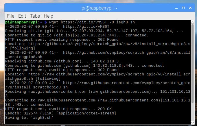
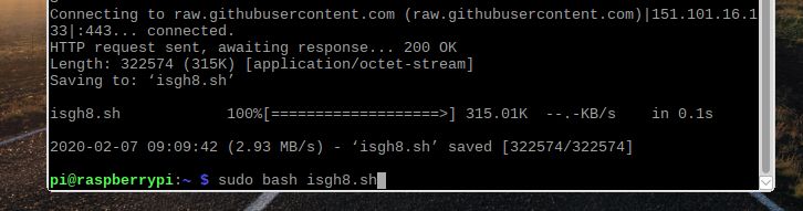
wget https://4tronix.co.uk/rover.sh -O rover.sh
bash rover.sh
This installs the following, which should be run for a command line (not in Idle etc.)
- Creates a folder home/pi/marsrover for all the example files and library module rover.py (the main library module)
- calibrateServos.py should be the first program you run. This ensures that the wheels are all pointing in the correct direction. You must use the terminal to run this and you will require sudo because it uses the LEDs as indicators. Run with sudo python calibrateServos.py. Then select each servo in turn using ‘0’ to ‘4’ keys and adjust the servo using the left and right arrow keys until it is straight. Press ‘s’ to save the calibration and exit the program.
- motorTest.py to demonstrate driving the motors. Must be run in a terminal, not from an IDE like Idle or Thonny. Use LXTerminal for this
- servoTest.py to demonstrate controlling the servos. Must be run in a terminal, not from an IDE like Idle or Thonny. Use LXTerminal for this
- ledTest.py flashes all LEDs through Red, Green, Blue and White. This must be run using sudo. ie: sudo python ledTest.py
- sonarTest.py shows the distance in cm for an obstacle using the ultrasonic distance sensor mounted on the mast head
- keypad.py shows the numeric value of each key pressed on th eoptional keypad
- driveRover.py is a basic driving program using the arrow keys to steer and move
Remote Control of Raspberry Pi
Check out the various interface methods for your Raspberry Pi. We prefer to use Real VNC desktop client on our PC with the built-in VNC server on the Pi Zero. See the Raspberry Pi Remote Access blog and scroll down to the VNC section.
Using the rover.py Library Module
To use this module, you must first import it into your program using
import rover
Then, before using any other functions you should call the init ( ) function to initialise all the variables used by the library. The init ( ) function has two optional parameters.
1. Default brightness of the LEDs. If omitted, this defaults to 40. So the following call will initialise the library and set the default brightness to 100:
rover.init (100)
2. Using the PiBit to convert a Microbit Rover to Pi Zero. This parameter is only needed if using a PiBit and causes the pins used to drive the motors to be swapped. For a PiBit, use:
rover.init(PiBit = True), or rover.init(100, PiBit=True)
Hot Tip:
As a special case, if you set the brightness to zero, then the LEDs are not initialised. As this would require use of the sudo command, it can be beneficial to call init (0) so that your program can be run without using sudo.
When your program has finished, it is good practice to close down everything tidily by calling:
rover.cleanup ( )
Motor Functions
- stop ( ): Stops all motors – coast slowly to a halt
- brake ( ): Stops all motors – brakes quickly
- forward (speed): Sets all motors to move forward at speed. 0 <= speed <= 100
- reverse (speed): Sets all motors to reverse at speed. 0 <= speed <= 100
- spinLeft (speed): Sets left and right motors to turn opposite directions at speed. 0 <= speed <= 100
- spinRight (speed): Sets left and right motors to turn opposite directions at speed. 0 <= speed <= 100
Fireled Functions
- setColor (color): Sets all LEDs to color – requires show()
- setPixel (ID, color): Sets pixel ID to color – requires show()
- show ( ): Updates the LEDs with state of LED array
- clear ( ): Clears all LEDs to off – requires show()
- rainbow ( ): Sets the LEDs to rainbow colors – requires show()
- fromRGB (red, green, blue): Creates a color value from R, G and B values
- toRGB (color): Converts a color value to separate R, G and B
- wheel (pos): Generates rainbow colors across 0-255 positions
UltraSonic Function
- getDistance ( ). Returns the distance in cm to the nearest reflecting object. 0 == no object.
Keypad Functions
- getKey ( ). Waits for a keypress on the optional touch keypad and returns the value of the keypad pressed. The relevant bit is set for any keys pressed (16 keys, so a 16-bit value is returned)
EEROM Functions
The onboard EEROM can store 1024 bytes of information. However, the first 16 bytes are used to stroe the servo calibration offsets, so “only” 1008 bytes are available to the user. The servo offset data is hidden, so the user data is addressed from 0 to 1007. Values return are signed bytes with values from -128 to +127 inclusive. This could be used for example to store a sequence of commands from the Keypad, creating a set of remote instructions, etc.
- readEEROM (Address). Returns the data byte stored at user address Address
- writeEEROM (Address, Data). Saves the data byte Data at the user address Address